Terminal equipment with table lamp function

A technology for terminal equipment and desk lamps, which is applied in the field of terminal equipment with the function of desk lamps, and can solve problems such as inconvenience

Pending Publication Date: 2018-03-20
全普半导体科技(深圳)有限公司
View PDF0 Cites 0 Cited by
  • Summary
  • Abstract
  • Description
  • Claims
  • Application Information

AI Technical Summary

Problems solved by technology

[0003] However, most of the terminals that modern people generally carry in their daily lives are mobile phones. However, when going out or in daily life, although the mobile phone has the function of a flashlight, it can only be used by hand, and it is inconvenient when you need to write or read documents.

Method used


Image

  • Terminal equipment with table lamp function
  • Terminal equipment with table lamp function
  • Terminal equipment with table lamp function

Examples


Embodiment 1

[0030] The mobile phone with the desk lamp function of the first embodiment has the usual functions of a mobile phone, a large touch screen, a power button, and different functional software can be displayed on the touch screen and human-computer interaction can be performed.

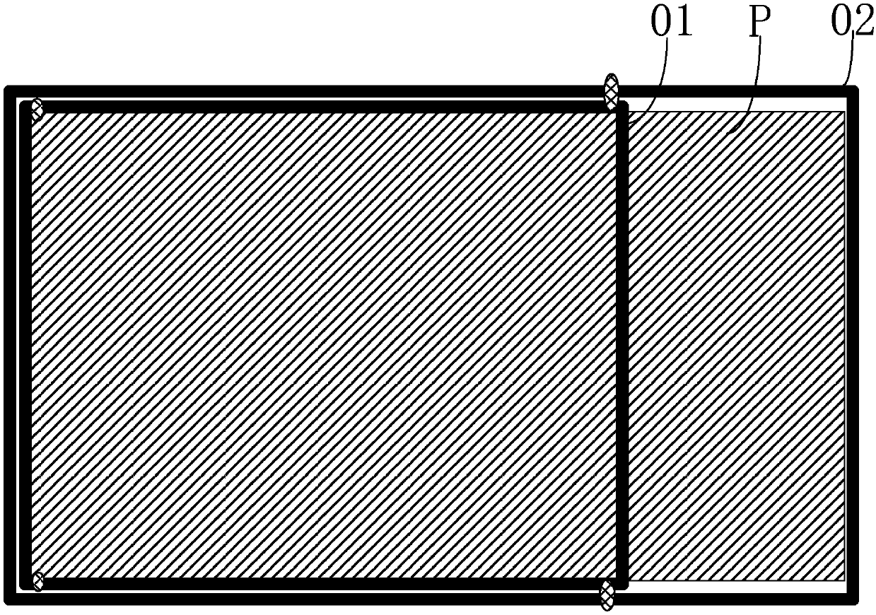
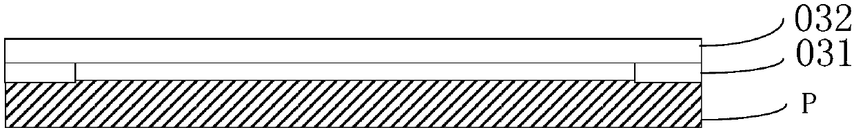
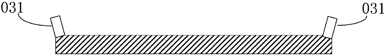
[0031] Please check Figure 1~2 , the mobile phone P back side of the present embodiment one has four rear shell layers, a pair of rear shell layers 031 and a pair of rear shell layers 032, the shape of each rear shell layer can be similar to the shape of the mobile phone P back, such as being rectangular; The side of each rear shell facing the back of the mobile phone P has a reflective film, and the edges of adjacent rear shells overlap, for example, the edges of the rear shell 031 and the adjacent rear shell 032 overlap; when performing the function of a desk lamp, each rear shell The shell opens to the outside of the phone, such as image 3 and 4 , so that the edges of each rear shell layer are in...

Embodiment 2

[0037] The structure and features of the rear shell layer in the second embodiment, as well as the relationship between the lamp hole and the lighting components can refer to the first embodiment, and will not be repeated here.

[0038] The difference between the mobile phone in the second embodiment and the mobile phone in the first embodiment above is that please refer to Figure 6 and 7 , the movable bracket is composed of three layers of suites 01', 02' and 03', the third layer of suite 03' is surrounded by the second layer of suite 02', the second layer of suite 02' is surrounded by the first layer of suite 01', the The three-layer kit 03', the second-layer kit 02' and the first-layer kit 01' are stacked on the side wall of the mobile phone P; and the first-layer kit 01' is formed by two bar frames, such as Figure 6 As shown, the same ends of the two bar racks are movably connected to the side wall of the mobile phone P, such as the middle area or the upper middle area ...


PUM


Abstract

The present invention provides a terminal device with the function of a desk lamp. By setting multiple rear shells on the back, the rear shells can be opened outwards in a default state to form a lampshade, which can be combined with the lighting software in the terminal device to turn on the lighting components. , used as a desk lamp. A movable bracket is also provided on the side wall of the terminal equipment, the movable bracket is covered on the side wall of the terminal equipment, one side of the movable bracket is connected to the bottom edge of the terminal equipment, or the movable bracket has multiple sets, and the multi-layer sets are stacked and surrounded, and the first layer The kit is composed of two bar frames, and the same ends of the two bar frames are movably connected to the side wall of the terminal equipment, so that when the movable bracket is opened, it constitutes a support frame. The invention integrates the function of the table lamp into the terminal equipment and expands the functions of the terminal equipment.

Description

technical field [0001] The present invention relates to the technical field of electronic terminal equipment, in particular to a terminal equipment with a desk lamp function. Background technique [0002] With the progress of human society, portable products are gradually favored by people. Traditional projectors are mostly bulky, heavy, and inconvenient to carry. Therefore, people have researched a micro-projector device, which can be integrated into terminal equipment, such as mobile phones, notebook computers, etc., thereby changing people's lifestyles. [0003] However, most of the terminals that modern people generally carry in their daily lives are mobile phones. However, when going out or in daily life, although the mobile phone has the function of a flashlight, it can only be used by hand, and it is inconvenient when you need to write or read documents. . Therefore, if the function of the desk lamp can be integrated on the mobile phone, a mobile phone can not only...

Claims


Application Information

Patent Timeline
Patent Type & Authority Applications(China)
IPC IPC(8): H04M1/02H04M1/04H04M1/22F21V7/00F21V19/00F21V21/10F21V33/00
CPCH04M1/026F21V7/0075F21V19/00F21V21/10F21V33/0052H04M1/04H04M1/22
Inventor 汪际军
Owner 全普半导体科技(深圳)有限公司
Why Eureka
Try Eureka