Manual pipe bending device

A pipe bending device and manual technology, applied in the field of manual pipe bending devices, can solve the problems of pipeline deflection, inability to bend small straight pipelines, and expensive molds.

Inactive Publication Date: 2018-03-23
BEIJING POWER MACHINERY INST
View PDF7 Cites 2 Cited by
  • Summary
  • Abstract
  • Description
  • Claims
  • Application Information

AI Technical Summary

Problems solved by technology

[0002] In actual production, when relying on the original bending tool to bend the pipeline manually, if the bending radius is too small, it is impossible to avoid the phenomenon of flattening at the bend of the pipeline; because the required clamping section is about 2 times the diameter of the pipe, it is impossible to bend small str...

Method used


Image

  • Manual pipe bending device
  • Manual pipe bending device
  • Manual pipe bending device

Examples


Embodiment Construction

[0028] Embodiments of the present invention will be described in detail below with reference to the accompanying drawings.

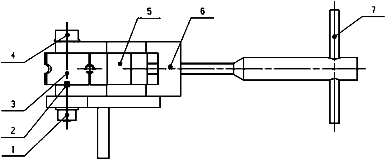
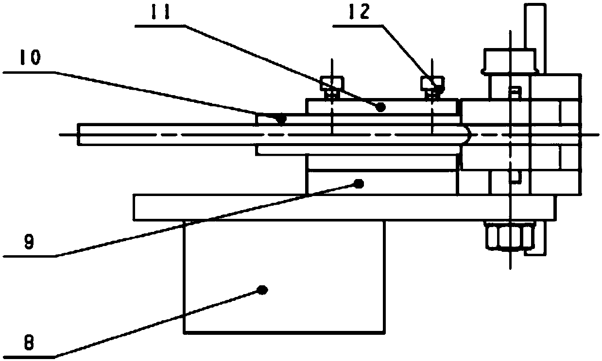
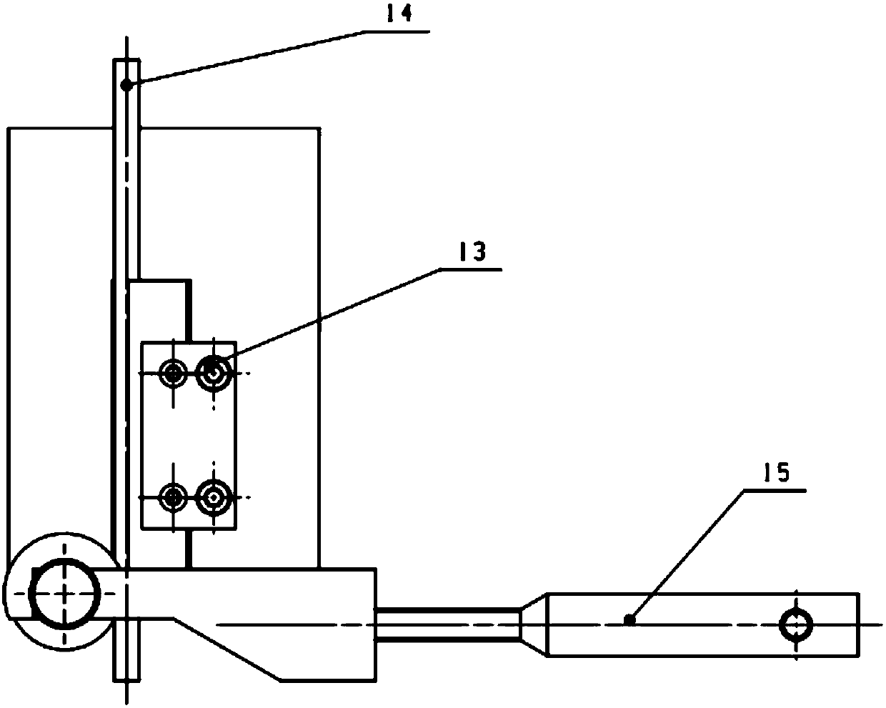
[0029] The main working parts of the manual pipe bending device include a bending die assembly, a clamping die assembly, and a compression die assembly. The bending die assembly includes the bending die 3 and the mandrel 4; the clamping die assembly includes the clamping die 5, the clamping die volume frame 6, the force arm 15 and the rod 7; Backing plate 9.

[0030] The bending die 3 is a cylinder with a side that is cut into a plane, and the central axis of the cylinder has a central through hole that cooperates with the mandrel 4 to be sleeved on the mandrel 4. On the circumference of the waist of the bending die 3 It has a groove matching the diameter of the pipeline. The clamping mold frame 6 is a fork-shaped frame. The cantilevered ends of the two fork arms have opposite through holes for being sleeved on the mandrel 4. The opposite inner sides of...


PUM


Abstract

The invention discloses a manual pipe bending device which comprises a base, a press die unit and a bending unit. The base is a workbench arranged on the ground. The press die unit is mounted on the face of the workbench and used for supporting a pipeline and cooperating with the bending unit for acting. The bending unit is mounted on a mandrel fixed to one corner of the front end of the workbenchface and can rotate around the mandrel so as to bend the pipeline. According to the manual pipe bending device, small straight segment and continuous bent pipelines can be bent. The phenomenon of pipeline deviation can be effectively avoided. The manual pipe bending device has the beneficial effects of being easy to machine, low in cost, high in adaptability, simple and convenient to operate andthe like.

Description

technical field [0001] The invention relates to a manual pipe bending device. Background technique [0002] In actual production, when relying on the original bending tool to bend the pipeline manually, if the bending radius is too small, it is impossible to avoid the phenomenon of flattening at the bend of the pipeline; because the required clamping section is about 2 times the diameter of the pipe, it is impossible to bend small straight pipes. Segment and continuous bending pipelines, and the original bending tooling has no effective guiding mechanism, and the pipelines are prone to deflection during bending, resulting in out-of-tolerance. It is usually processed by CNC pipeline forming machine, but it needs a specific mold, the mold is expensive, and the production cost is high. Contents of the invention [0003] The present invention aims to solve the above-mentioned technical problems in the prior art. Therefore, an object of the present invention is to propose a m...

Claims


Application Information

Patent Timeline
IPC IPC(8): B21D7/06B21D7/16
CPCB21D7/06B21D7/16
Inventor 王刚高宏波冯子晨朱慧荣李雪锋
Owner BEIJING POWER MACHINERY INST
Why Eureka
Try Eureka