Metal machining cutting device

A cutting device and metal processing technology, applied in metal processing equipment, shearing devices, accessories of shearing machines, etc., can solve the problems of manual cutting method errors, waste of labor costs, large manual cutting workload, etc. Excellent, high cutting efficiency

Pending Publication Date: 2018-03-23
昆山万马五金有限公司
View PDF3 Cites 0 Cited by
  • Summary
  • Abstract
  • Description
  • Claims
  • Application Information

AI Technical Summary

Problems solved by technology

At present, most metal cutting devices include a drive motor, a cutting wheel, a pressing rod and a cutting table. When cutting metal such as iron, the cutting wheel is driven by the driving motor to rotate, and the pressing rod is pressed down by the hand to make the cutting wheel in the rotating state Contact with the iron material on the cutting table to achieve the purpose of cutting, but this cutting device has the following defects: 1. It is necessary to artificially place the iron material on the cutting table to fix it. When it is necessary to cut the iron material into multiple sections, Not only is there a certain risk and a waste of labor costs; 2. When cutting multiple sections, there are errors in the artificial cutting method, and the iron material is not evenly cut; 3. The artificial cutting workload is large and the efficiency is low

Method used


Image

  • Metal machining cutting device
  • Metal machining cutting device
  • Metal machining cutting device

Examples


Embodiment Construction

[0018] The following will clearly and completely describe the technical solutions in the embodiments of the present invention with reference to the accompanying drawings in the embodiments of the present invention. Obviously, the described embodiments are only some, not all, embodiments of the present invention. Based on the embodiments of the present invention, all other embodiments obtained by persons of ordinary skill in the art without making creative efforts belong to the protection scope of the present invention.

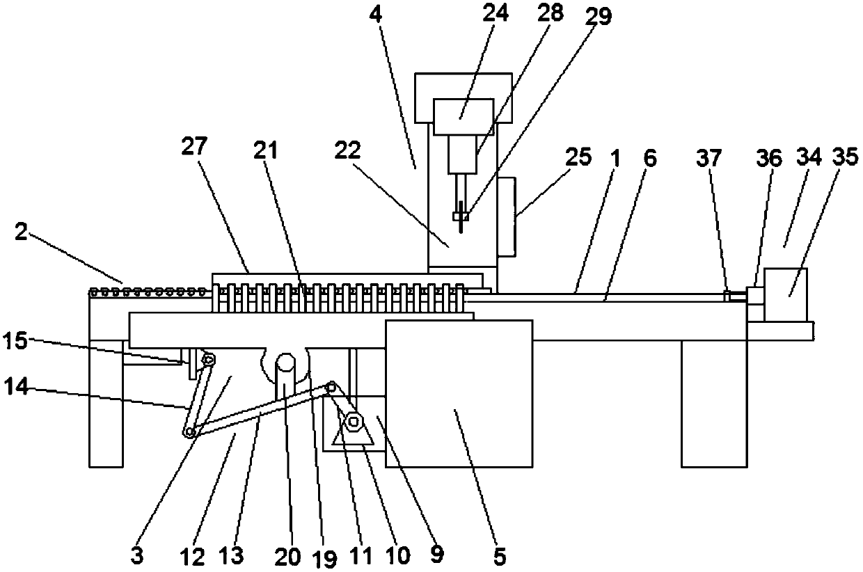
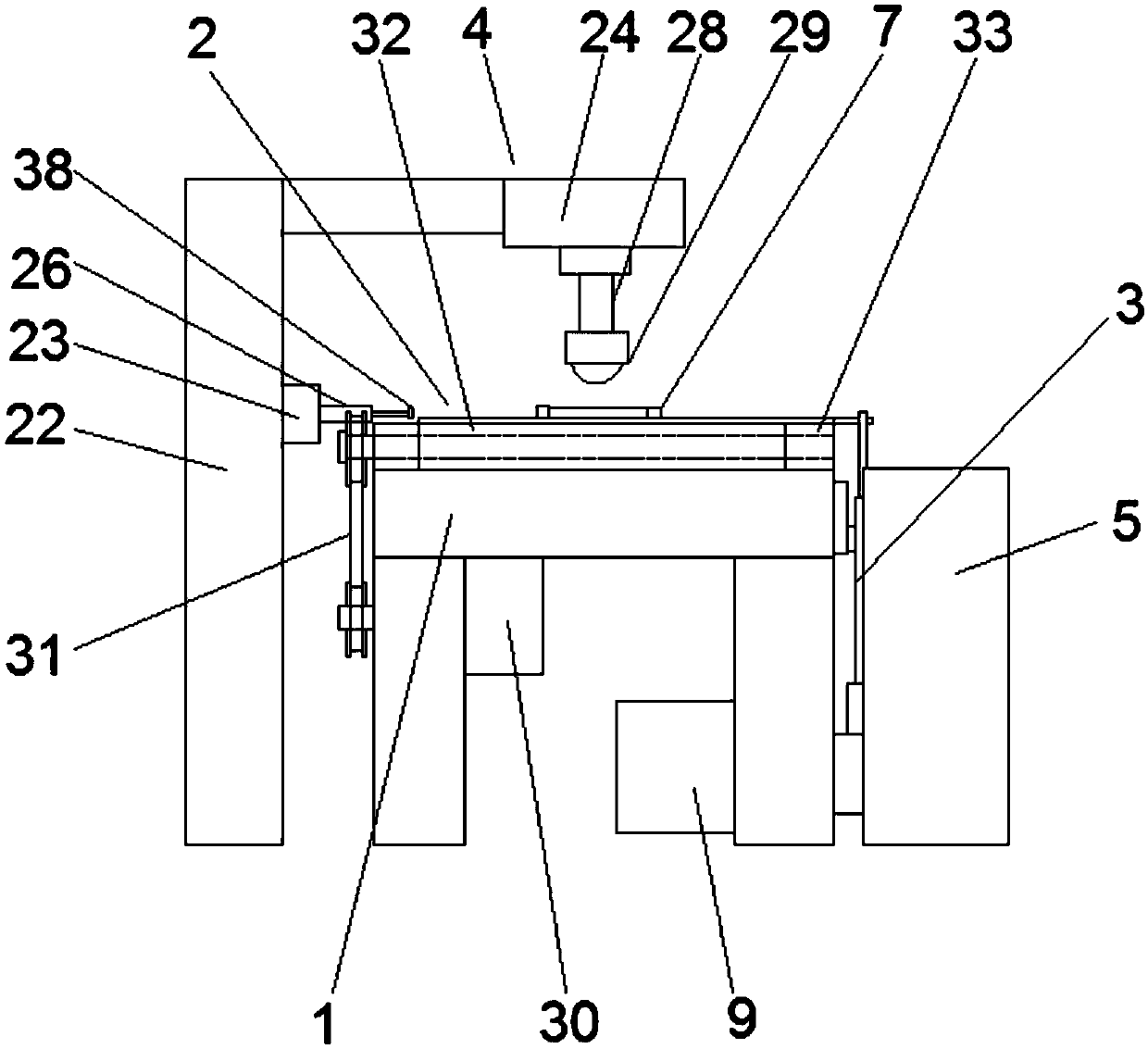
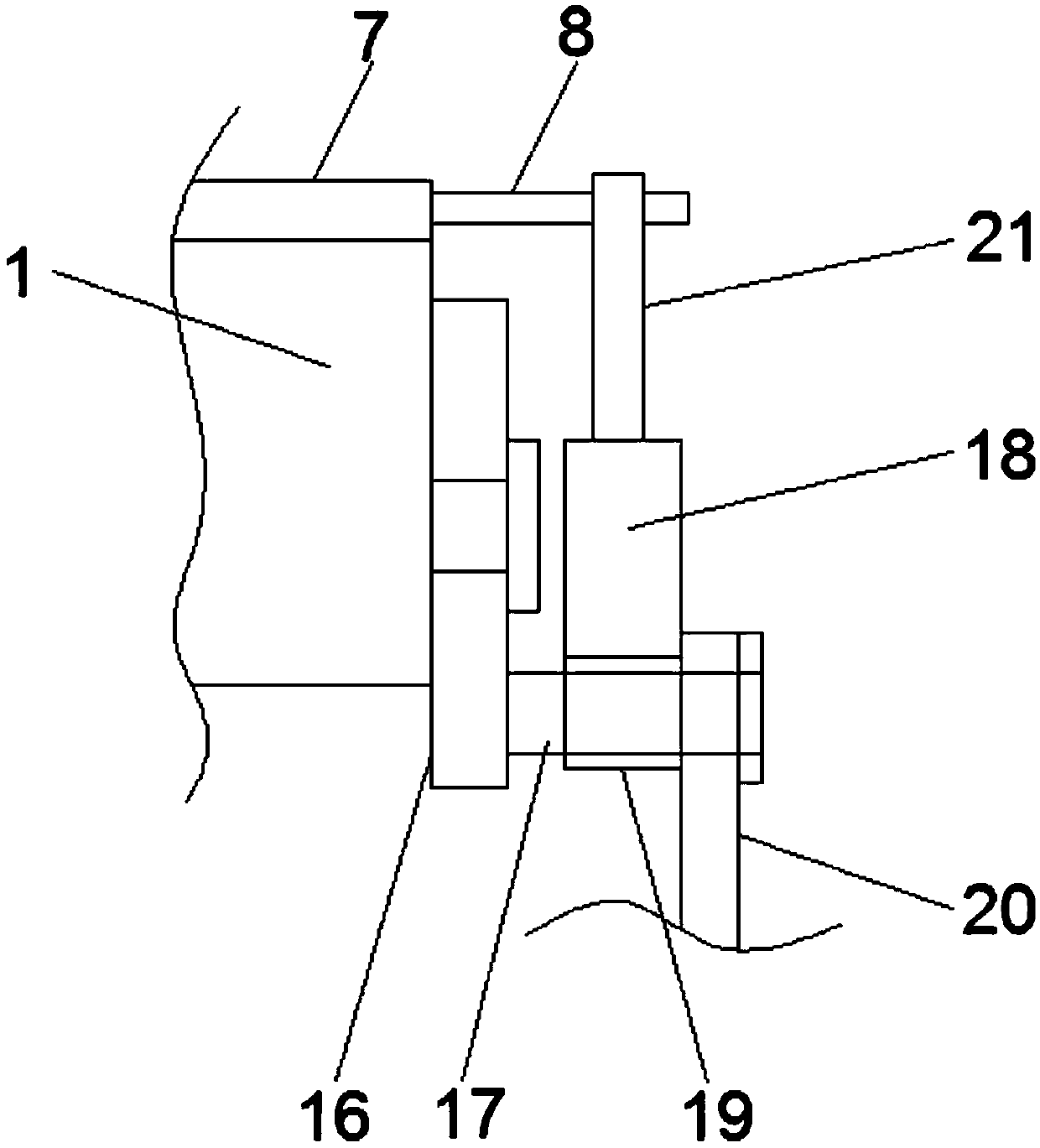
[0019] Such as Figure 1-3 As shown, the present invention provides a technical solution: a metal processing cutting device, including a cutting table 1, a first transmission mechanism 2, a second transmission mechanism 3, a cutting mechanism 4 and a receiving box 5, and the first transmission mechanism 2 is located at One end of the feed port of the cutting table 1 is provided with a chute 6 on the cutting table 1 and on one side of the first transmission mec...


PUM


Abstract

The invention discloses a metal machining cutting device. The metal machining cutting device comprises a cutting table, a first conveying mechanism, a second conveying mechanism, a cutting mechanism and a material collecting box; the first conveying mechanism is located at one end of a feeding inlet of the cutting table; a slide groove is formed in the position, located in one side of the first conveying mechanism, of the cutting table; the top of the cutting table is provided with a metal conveying seat matched with the slide groove; the second conveying mechanism is arranged on one side of the cutting table; one side of the metal conveying seat is provided with a plurality of fixing rods corresponding to the second conveying mechanism; and the second conveying mechanism comprises a driving motor, the driving motor is located on one side of the lower portion of the cutting table, one side of the driving motor is provided with a first fixing seat, and the end, penetrating through the first fixing seat, of an output shaft of the driving motor is fixedly connected with a first connection rod. The metal machining cutting device can achieve full-automatic metal cutting and collecting through cooperative operation of the first conveying mechanism, the second conveying mechanism, the cutting mechanism and the material collecting box, and is safe, reliable, good in quality and high incutting efficiency.

Description

technical field [0001] The invention relates to the field of metal processing and cutting, in particular to a metal processing and cutting device. Background technique [0002] Metal cutting machine is a kind of metal processing tool, which is widely used in many industries, such as construction, machinery manufacturing, shipbuilding and many other fields. At present, most metal cutting devices include a drive motor, a cutting wheel, a pressing rod and a cutting table. When cutting metal such as iron, the cutting wheel is driven by the driving motor to rotate, and the pressing rod is pressed down by the hand to make the cutting wheel in the rotating state Contact with the iron material on the cutting table to achieve the purpose of cutting, but this cutting device has the following defects: 1. It is necessary to artificially place the iron material on the cutting table to fix it. When it is necessary to cut the iron material into multiple sections, Not only is there a certa...

Claims


Application Information

Patent Timeline
Patent Type & Authority Applications(China)
IPC IPC(8): B23D19/00B23D33/02
CPCB23D19/00B23D33/02
Inventor 马佳佳
Owner 昆山万马五金有限公司
Why Eureka
Try Eureka