
Injection part cutting machine

A technology for injection molding parts and cutting machines, applied in metal processing and other directions, can solve the problems of increasing work error rate, one-time cutting completion, increasing labor costs, etc., and achieve the effect of reducing cutting steps, reducing production costs, and reducing labor costs.

Inactive Publication Date: 2018-03-23
王云龙
View PDF0 Cites 8 Cited by
  • Summary
  • Abstract
  • Description
  • Claims
  • Application Information

AI Technical Summary

Problems solved by technology

[0002] Some panel-shaped injection molded parts have many nozzles. The existing nozzle cutting equipment cannot cut all the nozzles of the injection molded parts at the same time. Multiple cuttings are required, which is inefficient and increases unnecessary labor costs. Cutting increases the error rate of work, resulting in increased production costs

Method used


Image

  • Injection part cutting machine
  • Injection part cutting machine
  • Injection part cutting machine

Examples


Embodiment Construction

[0023] Below in conjunction with accompanying drawing and embodiment of description, specific embodiment of the present invention is described in further detail:

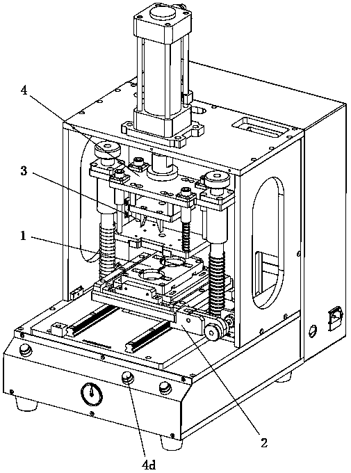
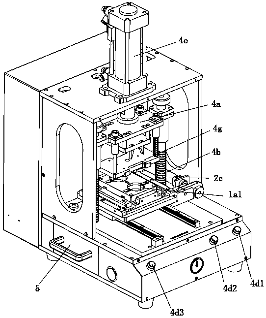
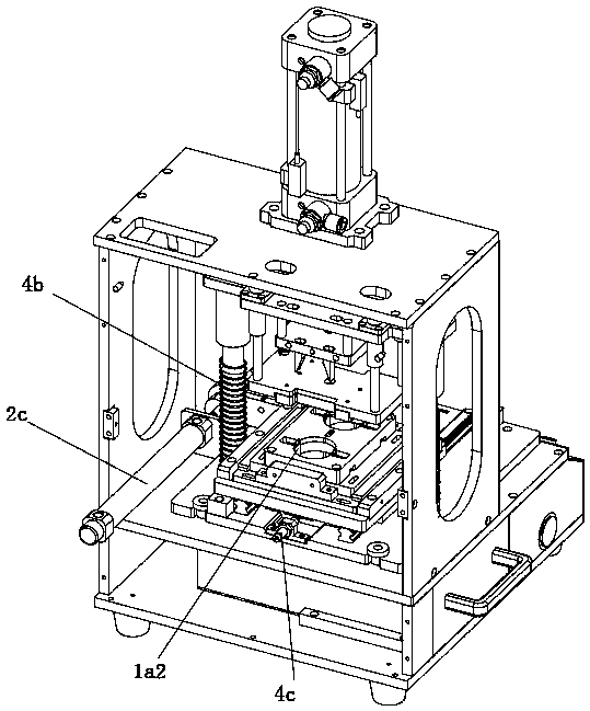
[0024] refer to Figure 1 to Figure 8 The injection molded parts cutting machine shown in the figure includes a positioning jig 1 for clamping the injection molded parts, a moving mechanism 2 for driving the positioning jig 1 to move, and a cutting assembly for cutting the nozzle of the injection molded parts 3 and the lifting assembly 4 that drives the cutting assembly 3 to lift up and down. The positioning fixture 1 includes a holding plate 1a for placing the injection molded parts and a clamping assembly 1a1 for clamping the injection molded parts. The moving mechanism 2 includes a The sliding assembly of the fixture 1 and the driving assembly for driving the positioning fixture 1 to slide on the sliding assembly, the lifting assembly 4 includes a lifting platform 4a and a buffer assembly 4b, and also includes a ...


PUM


Abstract

The invention relates to the field of cutting equipment, in particular to a cutting machine for injection molded parts, which includes a positioning fixture, a moving mechanism, a cutting assembly and a lifting assembly. A clamping component for an injection molded part, the moving mechanism includes a sliding component for sliding and matching a positioning fixture and a driving component for driving the positioning fixture to slide on the sliding component, and the lifting component includes a lifting platform and a buffer component, It also includes a control device, the control device includes a sensor assembly, a manual control button and a controller, and the sensor assembly and the manual control button are both electrically connected with the controller. The nozzle is cut, and the cutting is completed at one time, which reduces the cutting steps, improves the cutting efficiency, reduces unnecessary labor costs, reduces the error rate of work, and reduces unnecessary production costs.

Description

technical field [0001] The invention relates to the field of cutting equipment, in particular to a cutting machine for injection molded parts. Background technique [0002] Some panel-shaped injection molded parts have many nozzles. The existing nozzle cutting equipment cannot cut all the nozzles of the injection molded parts at the same time. Multiple cuttings are required, which is inefficient and increases unnecessary labor costs. Cutting increases the error rate of work, resulting in increased production costs. Contents of the invention [0003] The object of the present invention is to provide an injection molded part cutting machine for the deficiencies of the prior art. [0004] In order to solve the above problems, the present invention provides the following technical solutions: [0005] An injection molded parts cutting machine, including a positioning jig for clamping an injection molded part, a moving mechanism for driving the positioning jig to move, a cutti...

Claims


Application Information

Patent Timeline
Patent Type & Authority Applications(China)
IPC IPC(8): B29C45/38B26D7/02B29C45/76
CPCB29C45/382B26D7/02B29C45/76
Inventor 王云龙
Owner 王云龙
Learn More