
Method for reducing opening shock of ram air parachute

A technology of parafoil and parachute rope is applied in the field of reducing the impact of ramming parafoil opening, which can solve the problems such as difficulty in matching the size of the closing sliding cloth, difficulty in design, and complex structure of the multi-stage deceleration system.

Active Publication Date: 2018-03-23
AEROSPACE LIFE SUPPORT IND LTD
View PDF5 Cites 3 Cited by
  • Summary
  • Abstract
  • Description
  • Claims
  • Application Information

AI Technical Summary

Problems solved by technology

[0003] In order to reduce the impact of the ram parachute opening, there are generally two methods. One is to use multiple parachutes to form a multi-stage deceleration system, but the structure of the multi-stage deceleration system is complicated and the reliability is reduced; The slider controls the opening of the parachute, but it is difficult to match the size of the closing slider. Generally, the size of the closing slider and the size of the wing surface are estimated, and a ratio is set. However, the load reduction effect of the slider needs a lot of experiments to evaluate, especially the wing surface When it is an irregular shape such as an ellipse, the design of the sliding cloth is more difficult

Method used

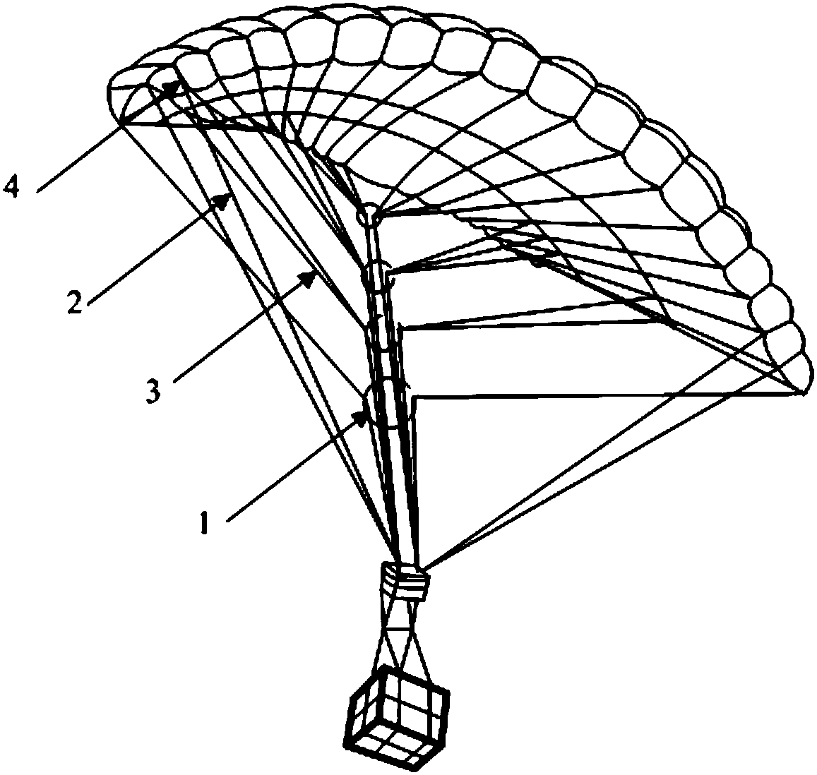

Image

  • Method for reducing opening shock of ram air parachute
  • Method for reducing opening shock of ram air parachute
  • Method for reducing opening shock of ram air parachute

Examples


Embodiment Construction

[0016] The present invention will be further described below in conjunction with the accompanying drawings and embodiments.

[0017] Such as figure 1 with figure 2 As shown, a method for reducing the impact of a stamped parafoil opening is to use the air inlet paracord at the front edge of the stamped parafoil 4 as the non-binding parachute 2, and the remaining parachute as the binding parachute 3, and the binding parachute 3 from The trailing edge to the front edge of the stamping parafoil 4 is divided into several groups in turn and each group of paracords is symmetrical about the center of the wing surface of the stamping parafoil 4 (the self-symmetric center plane of the stamping parafoil 4), and each group of paracords is composed of a The binding ropes 1 are bundled together and the binding points are located at the center of the airfoil. The positions of all binding points move down from the trailing edge to the front edge, and the strength of all binding ropes 1 decr...


PUM


Abstract

The invention relates to a method for reducing the opening shock of a ram air parachute. The method for reducing the opening shock of the ram air parachute comprises the following steps that an air inlet parachute cord at the front edge of the ram air parachute is used as a non-bundled parachute cord and the rest parachute cords of the ram air parachute are used as bundled parachute cords; the bundled parachute cords are divided into a plurality of groups in sequence from the rear edge of the ram air parachute to the front edge of the ram air parachute, wherein the parachute cords in each group are symmetric relative to the center of the airfoil of the ram air parachute; the parachute cords in each group are bundled and tightened together by using a binding rope and the binding point is atthe center of the airfoil; the positions of all binding points move down in sequence from the rear edge to the front edge; the strengths of all binding ropes are reduced in sequence from the rear edge to the front edge; when the ram air parachute is unfolded, an air chamber is unfolded to be inflated from the front edge and the rear edge under the driving of the non-bundled air inlet parachute cord; in the inflating process, the parachute cords, which are tensioned in sequence from the front edge to the rear edge, are enabled to snap the binding ropes in sequence from bottom to top; and meanwhile, the air chamber is gradually inflated until the air chamber is full of air. According to the method for reducing the opening shock of the ram air parachute, sliding cloth does not need to be closed up because the ram air parachute is unfolded step by step, the layer level of the parachute system can be reduced, and the implementation is simple.

Description

technical field [0001] The invention belongs to the field of airdrop parachutes, and in particular relates to a method for reducing the impact of punching parachute opening. Background technique [0002] Stamped parafoil is a new type of parachute. It is a kind of flexible aircraft similar to the airfoil that is sewn by the upper and lower layers of the micro air permeability material. The initial state of the stamped parafoil is folded and packaged in a flexible state. , as far as the current speed of the airdrop carrier is concerned, the stamped parafoil is generally opened under the condition of a relatively large parachute opening speed. large shock loads. [0003] In order to reduce the impact of the ram parachute opening, there are generally two methods. One is to use multiple parachutes to form a multi-stage deceleration system, but the structure of the multi-stage deceleration system is complicated and the reliability is reduced; The slider controls the opening of ...

Claims


Application Information

Patent Timeline
Patent Type & Authority Applications(China)
IPC IPC(8): B64D17/62
CPCB64D17/62
Inventor 李轲雷小平邹长庚
Owner AEROSPACE LIFE SUPPORT IND LTD
Learn More