A multi-workpiece ion beam polishing system and method

An ion beam and multi-workpiece technology, applied in the field of ion beam polishing, can solve the problems of not effectively improving processing efficiency, limited clamping positions of fixtures, affecting production efficiency, etc., so as to reduce the level of moving devices and reduce the disassembly and assembly of workpieces. , the effect of improving production efficiency

Active Publication Date: 2021-03-12
长沙埃福思科技有限公司
View PDF7 Cites 0 Cited by
  • Summary
  • Abstract
  • Description
  • Claims
  • Application Information

AI Technical Summary

Problems solved by technology

[0004] However, the existing ion beam processing system adopts a vacuum structure, which is very troublesome to assemble and disassemble. The current ion beam processing system, whether it is a single vacuum chamber or a double vacuum chamber design, the clamping position of the tooling fixture is limited, and only one workpiece can be clamped at a time for processing, and the processing efficiency has not been effectively improved.

Method used


Image

  • A multi-workpiece ion beam polishing system and method
  • A multi-workpiece ion beam polishing system and method
  • A multi-workpiece ion beam polishing system and method

Examples


Embodiment 1

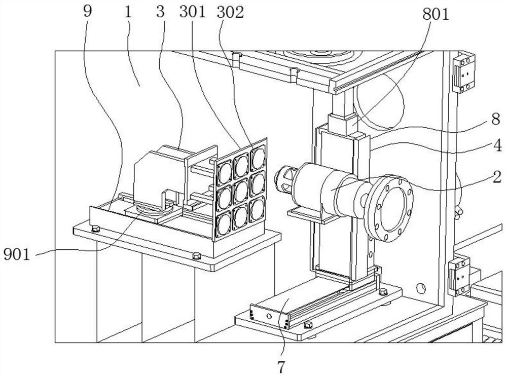
[0041] see figure 1 , image 3 , Figure 4 , the present embodiment is a multi-workpiece ion beam polishing system, the vacuum chamber is a single vacuum chamber, and the vacuum chamber 1 is provided with an ion source 2 required for generating an ion beam, a clamp 3 for clamping a workpiece 10, and a The controlled motion mechanism 4 holds a plurality of workpieces 10 on the fixture 3 at the same time.

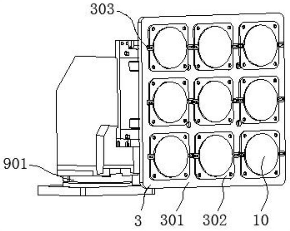
[0042] In this embodiment, the jig 3 includes a clamping plate 301, on which a plurality of positioning plates 302 are connected, and the positioning plate 302 is provided with a structure for fixing the workpiece.

[0043] In this embodiment, the positioning plate 302 is determined according to the shape of the workpiece 10 and is set in a circular shape, and the structure for fixing the workpiece is a latch 303 .

[0044] In this embodiment, the motion mechanism 4 includes an X-direction motion unit 7 , a Y-direction motion unit 8 , and a Z-direction motion unit 9 that a...

Embodiment 2

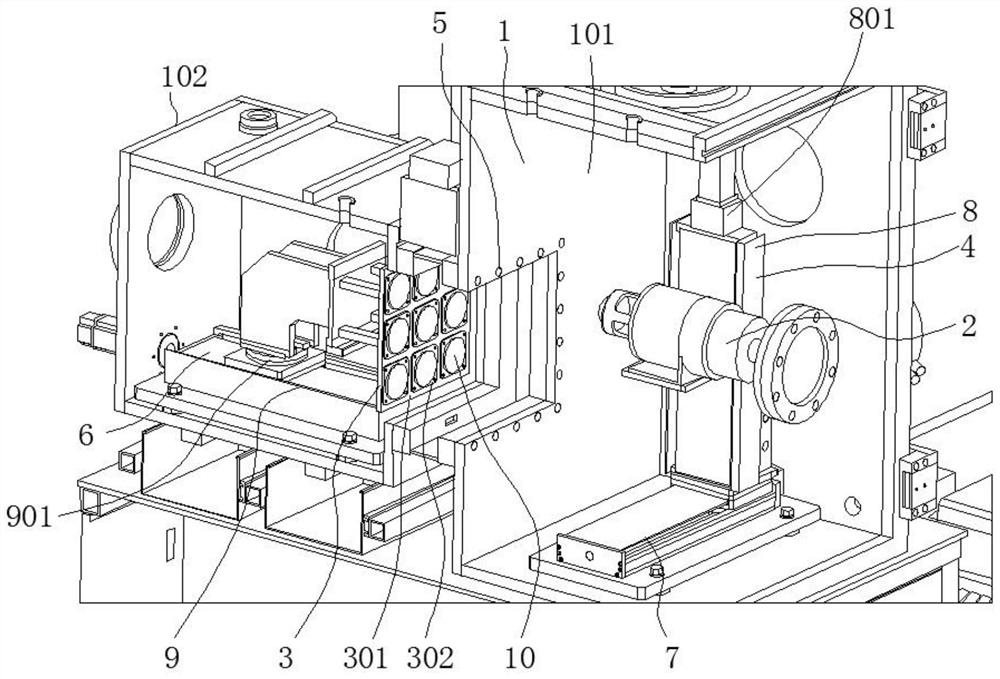
[0060] The difference from Embodiment 1 is that the vacuum chamber in this embodiment is a double vacuum chamber, and the vacuum chamber 1 is divided into a main vacuum chamber 101 and a secondary vacuum chamber 102, and a control main chamber is installed between the main vacuum chamber 101 and the secondary vacuum chamber 102. , The gate valve 5 for switching on and off the auxiliary vacuum chamber, the ion source 2 is located in the main vacuum chamber 101, and the fixture 3 for clamping multiple workpieces is installed in the auxiliary vacuum chamber 102 to load and unload multiple workpieces.

[0061] In this embodiment, the main and auxiliary vacuum chambers are provided with docking guide rails 6 , and the multi-workpiece fixture 3 enters and exits the main vacuum chamber from the auxiliary vacuum chamber through the docking guide rails 6 .

[0062] In this embodiment, the Z-direction movement unit 9 and the docking guide rail 6 are the same device.

[0063] In this emb...


PUM


Abstract

The invention discloses a multiple-workpiece ion beam polishing system and method. The multiple-workpiece ion beam polishing system comprises a vacuum chamber. A required ion source, a clamp and a movement mechanism are arranged in the vacuum chamber. The ion source generates an ion beam, the clamp is used for clamping workpieces, and the movement mechanism is used for conducting machining control. The multiple workpieces are clamped on the clamp at the same time. According to the multiple-workpiece ion beam polishing system and method, the multiple-workpiece clamp is adopted, the multiple workpieces are clamped at one time, and therefore the time, required by vacuum pumping and debugging of a single workpiece, of a machine is omitted, machining of the multiple surfaces can be conducted onthe multiple workpieces at the same time, the machining time and the machining cost are greatly saved, and the machining efficiency is greatly improved. According to the multiple-workpiece ion beam polishing method, the multiple-station clamp is arranged in the polishing system, the multiple workpieces can be simultaneously clamped to be machined at the same time, and therefore the production efficiency of the machine is further improved. In addition, the distances between the multiple workpieces are judged, an appropriate machining method is adopted, and therefore the purpose of polishing the workpieces on the same clamp at the same time can be achieved.

Description

technical field [0001] The invention relates to the technical field of ion beam polishing, in particular to a multi-workpiece ion beam polishing system and method. Background technique [0002] Ion beam refers to a group of ions that move in almost the same direction at approximately the same speed. The ion beam modification process uses ion beams to modify the shape of the workpiece. Borrowing ion beams for processing can improve processing accuracy and ensure product quality. The beam polishing process is one of the ion beam modification processes. [0003] At present, the ion beam modification processing equipment often adopts a single vacuum chamber design or a double vacuum chamber design. Similar to the general processing system, the ion beam processing system is equipped with a moving mechanism, an ion source and a workpiece fixture. [0004] However, the existing ion beam processing system adopts a vacuum structure, which is very troublesome to assemble and disassem...

Claims


Application Information

Patent Timeline
Patent Type & Authority Patents(China)
IPC IPC(8): B24B1/00B24B41/06B24B41/00
CPCB24B1/00B24B41/00B24B41/06
Inventor 不公告发明人
Owner 长沙埃福思科技有限公司
Why Eureka
Try Eureka