

Terminal equipment connection device
A technology for connection devices and terminal equipment, which is applied to parts, connections, coupling devices, etc. of connection devices. It can solve problems such as easy damage to equipment interfaces and imperfect protection measures for terminal equipment interfaces, so as to avoid exposure risks and improve user experience. Experience and easy-to-use effects
- Summary
- Abstract
- Description
- Claims
- Application Information
AI Technical Summary
Problems solved by technology
Method used
Image

Examples
Embodiment 1
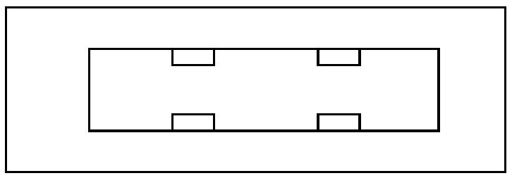
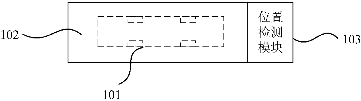
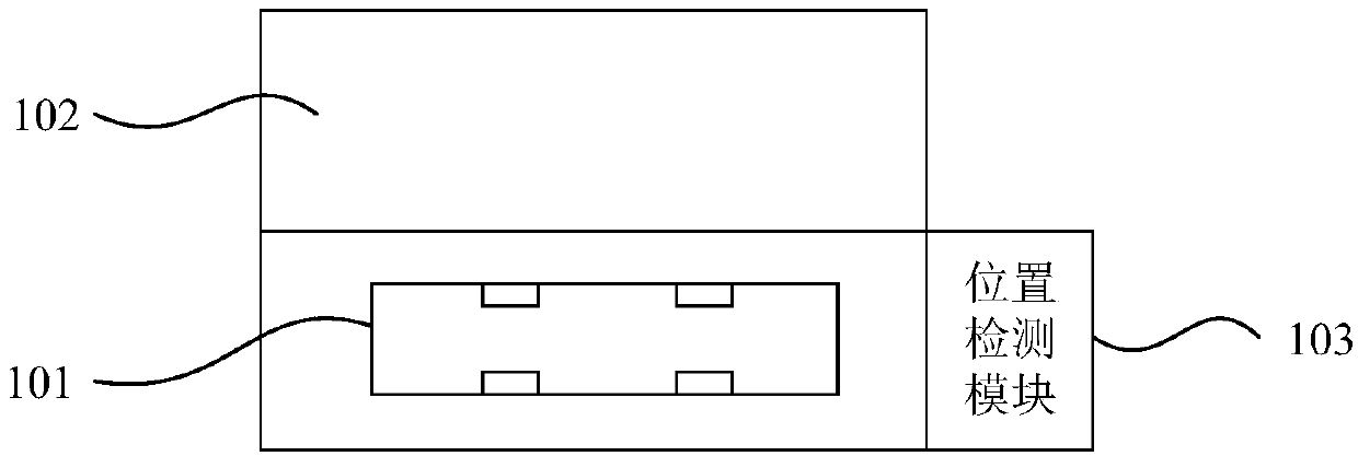
[0025] The terminal device connection device of this embodiment, such as figure 2 , image 3 As shown, including: equipment interface 101 ( figure 2 Among them, because the device interface 101 is covered by the shielding cover 102, it is represented by a dotted line), the shielding cover 102 covering the device interface 101, the position detection module 103 arranged at the end of the device interface 101, the main control unit (set on the The interior of the housing of the terminal equipment connection device, not shown in the figure). The position detection module is used to detect the position change of the external device relative to the device interface 101. The main control unit is electrically connected to the position detection module to obtain the position change and open or close the shielding cover 102 according to the position change.
[0026] The shielding cover 102 is in a closed state in the initial state, and plays the role of waterproofing, dustproofing,...
Embodiment 2
[0030] On the basis of the terminal device connection device in Embodiment 1, the terminal device connection device in this embodiment provides an optional implementation of the position detection module: Figure 4 , Figure 5 As shown, the position detection module 103 includes a metal detector 1031, and the metal detector 1031 can detect the metal material on the external device, and can detect the distance between the metal material and the metal detector 1031, that is, the distance between the metal material and the metal detector 1031. The distance of the device interface 101. When the position of the metal material to the equipment interface 101 is from far to near, the main control unit immediately judges that the external equipment is approaching the equipment interface 101 and wishes to be inserted into the equipment interface 101, and the main control unit then controls the electromechanical connection device to open the shielding cover 102 (such as Figure 5 shown)...
Embodiment 3
[0034] On the basis of Example 1, such as Figure 6 , Figure 7 As shown, an optional implementation manner of the position detection module of the terminal device connection device in this embodiment includes a metal detector 1031 and a proximity sensor 1032 . Metal detector 1031 will not respond to metal objects that remain stationary relative to metal detector 1031 . When the metal detector 1031 detects that a metal part on the external device moves near the device interface 101 , it transmits a signal detecting the metal part to the main control unit, and the main control unit turns on the proximity sensor 1032 . The proximity sensor 1032 includes, but is not limited to, a capacitive proximity sensor, an inductive proximity sensor, or a photoelectric proximity sensor. The proximity sensor 1032 can detect the position change of the external device relative to the device interface 101. For example, the inductive proximity sensor can detect the displacement of the metal obj...
PUM
 Abstract
Description
Claims
Application Information