Controller-free self-startup permanent magnetism auxiliary synchronous reluctance machine

A technology for auxiliary synchronous and reluctance motors, applied to synchronous motors with stationary armatures and rotating magnets, synchronous machines, magnetic circuits, etc., can solve the problems of high cost, no self-starting operation function, etc., and achieve less usage , Prevent the risk of high temperature demagnetization, easy to weaken the effect of magnetic field expansion

Inactive Publication Date: 2018-03-23
WOLONG ELECTRIC GRP CO LTD
View PDF4 Cites 13 Cited by
  • Summary
  • Abstract
  • Description
  • Claims
  • Application Information

AI Technical Summary

Problems solved by technology

[0002] At present, the general reluctance motor needs to be equipped with a special controller to operate, and has no self-starting operation function. At the same time, for the general permanent magnet synchronous motor, a large amount of rare earth permanent magnet materials are used, resulting in high cost

Method used


Image

  • Controller-free self-startup permanent magnetism auxiliary synchronous reluctance machine
  • Controller-free self-startup permanent magnetism auxiliary synchronous reluctance machine
  • Controller-free self-startup permanent magnetism auxiliary synchronous reluctance machine

Examples


Embodiment Construction

[0023] The technical solution of the present invention will be further described in detail below in conjunction with the accompanying drawings.

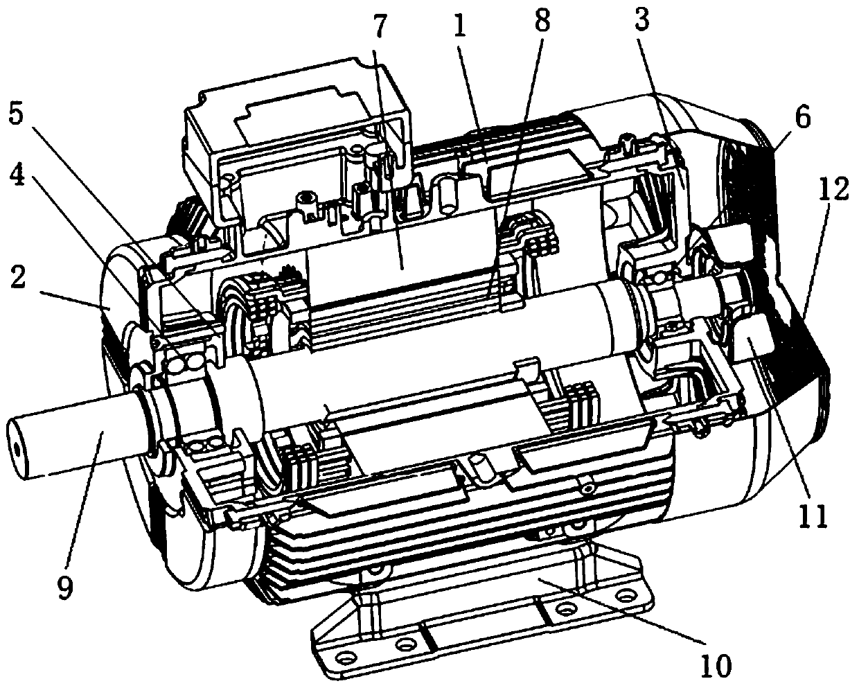
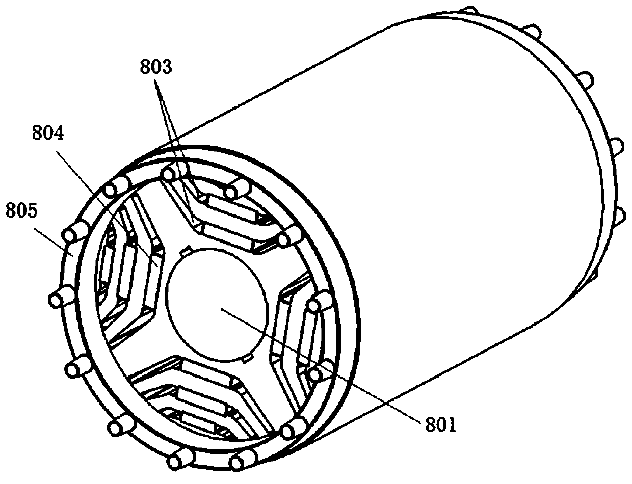
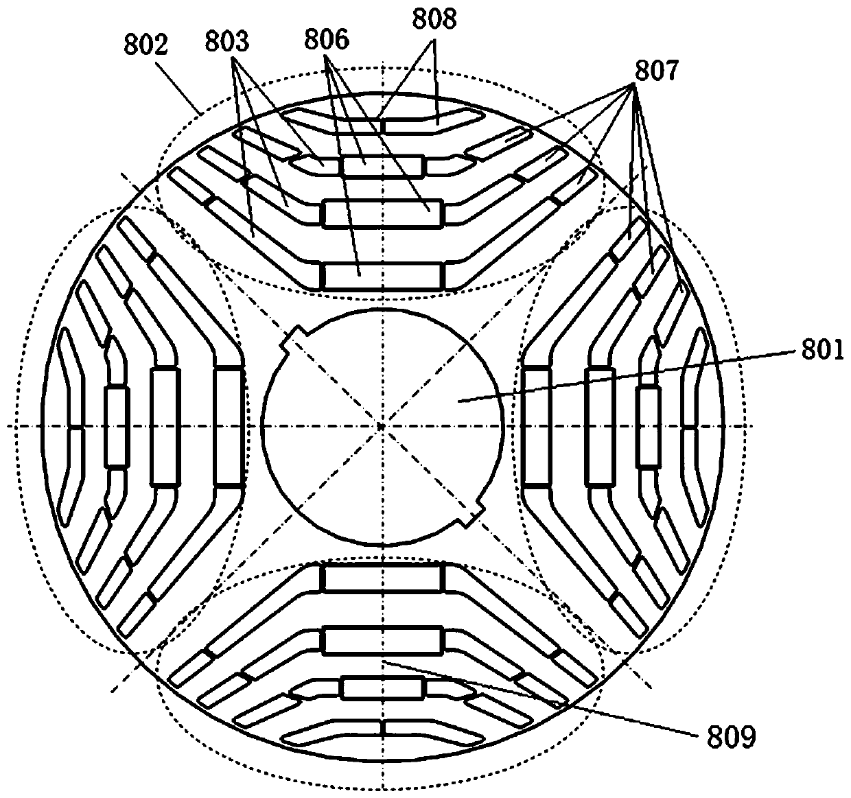
[0024] Such as Figure 1-3 As shown, a controllerless self-starting permanent magnet assisted synchronous reluctance motor, including a machine base 1, a front end cover 2, a rear end cover 3, a front bearing 4, a front bearing inner cover 5, a rear bearing 6, and a rear bearing inner cover , wire stator 7, rotor core 8, rotating shaft 9, feet 10, fan blades 11, wind cover 12, the rotor core 8 is formed by stacking iron core punches with 4 magnetic poles 802 evenly distributed around it, the described The geometric center line of the magnetic pole 802 is the magnetic pole axis 809, the center of the iron core punching sheet is provided with a rotating shaft hole 801, and each magnetic pole 802 is provided with three permanent magnets 804 arranged along the magnetic pole axis 809, and each permanent magnet 804 Reluctance slots 803 ar...


PUM


Abstract

A controller-free self-startup permanent magnetism auxiliary synchronous reluctance machine relates to the motor field. At present, a general reluctance machine needs to be configured with a special-purpose controller to operate and does not have a self-startup operation function, at the same time, for a general permanent magnet synchronous motor, a lot of rare earth permanent magnetism materialsare adopted, so that the cost is higher. A rotor iron core of the present invention is formed by laminating the iron core punching sheets around and on which a plurality of magnetic poles surround andare distributed uniformly, the geometric center lines of the magnetic poles are the magnetic pole axes, and the rotating shaft holes are arranged in the centers of the iron core punching sheets. Theplurality of magnetic pole are all equipped with the permanent magnets which are arranged along the magnetic pole axes and of which the numbers are same, the reluctance grooves are arranged at the twosides of each permanent magnet, and a cast-in aluminum squirrel cage is arranged at the periphery of the rotor iron core located at the outer sides of the reluctance grooves of the iron core punchingsheets. According to the technical scheme, by adopting a mode of combining the permanent magnet synchronous motor and the synchronous reluctance machine, and combining the cast-in aluminum squirrel cage, the usage of the permanent magnetism materials is reduced, the motor can operate very well on the condition of not having a controller, and the cost of the motor is reduced substantially.

Description

technical field [0001] The invention relates to the field of motors, in particular to a self-starting permanent magnet assisted synchronous reluctance motor without a controller. Background technique [0002] At present, the general reluctance motor needs to be equipped with a special controller to operate, and has no self-starting operation function. At the same time, for the general permanent magnet synchronous motor, a large amount of rare earth permanent magnet materials are used, resulting in high cost. Contents of the invention [0003] The technical problem to be solved and the technical task proposed by the present invention are to perfect and improve the existing technical solutions, and to provide a self-starting permanent magnet assisted synchronous reluctance motor without a controller for the purpose of reducing costs. For this reason, the present invention takes the following technical solutions. [0004] A self-starting permanent magnet assisted synchronous...

Claims


Application Information

Patent Timeline
Patent Type & Authority Applications(China)
IPC IPC(8): H02K21/46H02K21/14H02K1/27
CPCH02K21/46H02K1/2766H02K21/14
Inventor 王国龙胡吉亮严伟灿孙军建王斌
Owner WOLONG ELECTRIC GRP CO LTD
Why Eureka
Try Eureka