
Automatic cutting and grinding equipment for low-carbon steel pipe for splicing of building structure grid frame

A building structure, cutting and grinding technology, applied in other manufacturing equipment/tools, manufacturing tools, etc., can solve the problems of poor grinding effect of steel pipe cuts, irregular steel pipe cuts, and inability to fix steel pipes.

Inactive Publication Date: 2018-03-27
吴秋敏
View PDF0 Cites 18 Cited by
  • Summary
  • Abstract
  • Description
  • Claims
  • Application Information

AI Technical Summary

Problems solved by technology

[0003] In order to solve the above problems, the present invention provides an automatic cutting and grinding equipment for low-carbon steel pipes used for splicing building structure grids, which can solve the problem that existing steel pipes cannot be firmly fixed when cutting steel pipes, and the steel pipes after cutting The incision is not neat, the steel pipe incision needs to be manually polished, the steel pipe incision grinding effect is poor, the position of the steel pipe needs to be corrected manually before welding, and the position of the steel pipe will have errors after correction; it can realize the fixed angle cutting of the steel pipe, and the Grinding the steel pipe cut after cutting, and splicing the polished steel pipe together accurately. It can fix the steel pipe firmly, cut the steel pipe cut neatly, automatically grind the steel pipe cut, and the steel pipe cut has a good grinding effect. The position of the steel pipe is automatically corrected before the steel pipe is welded, and there is no error in the position of the steel pipe after correction, etc.

Method used


Image

  • Automatic cutting and grinding equipment for low-carbon steel pipe for splicing of building structure grid frame
  • Automatic cutting and grinding equipment for low-carbon steel pipe for splicing of building structure grid frame
  • Automatic cutting and grinding equipment for low-carbon steel pipe for splicing of building structure grid frame

Examples


Embodiment Construction

[0029] In order to make the technical means, creative features, objectives and effects achieved by the present invention easy to understand, the present invention will be further described below in conjunction with specific illustrations. It should be noted that, in the case of no conflict, the embodiments in the present application and the features in the embodiments can be combined with each other.

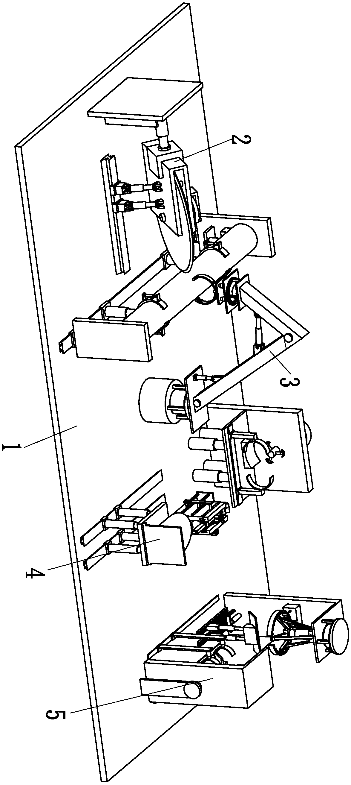
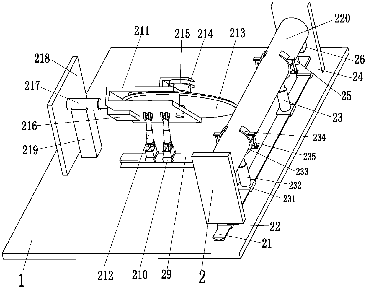
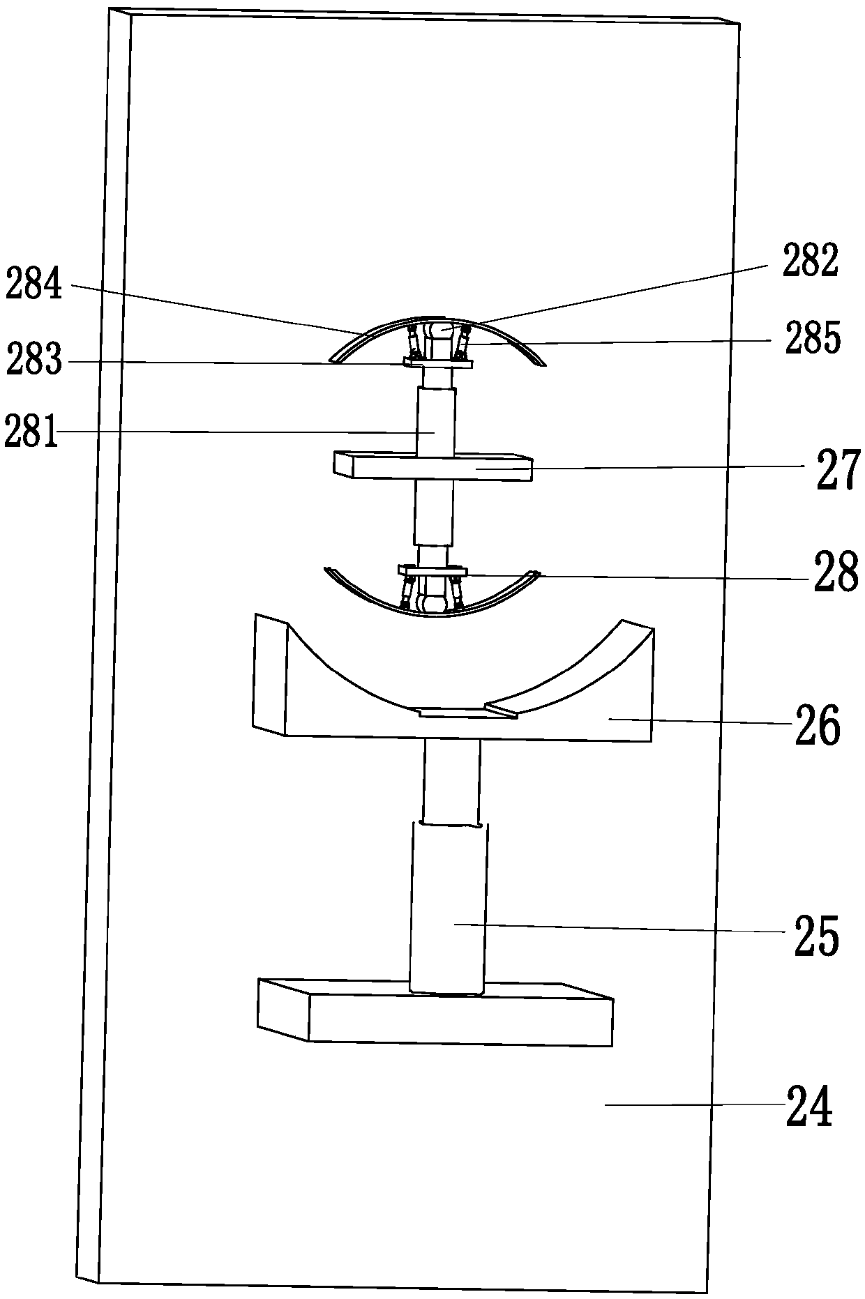
[0030] Such as Figure 1 to Figure 11 As shown, a low-carbon steel pipe automatic cutting and grinding equipment for splicing building structure grids includes a support base plate 1, a cutting device 2, a clamping device 3, a grinding device 4 and a fixing device 5. The left end of the support base plate 1 The cutting device 2 is installed on the top, the gripping device 3 is located on the right side of the cutting device 2, the gripping device 3 is installed on the top of the supporting base 1, the grinding device 4 is connected with the middle part of the supporting base 1, ...


PUM


Abstract

The invention relates to an automatic cutting and grinding equipment for low-carbon steel pipes used for splicing building structure grids, which includes a supporting base plate, a cutting device, a clamping device, a grinding device and a fixing device, and a cutting device is installed on the top of the left end of the supporting base plate , the clamping device is installed on the top of the support base plate, the grinding device is connected with the middle part of the support base plate, and the fixing device is installed on the top right side of the support base plate. The present invention can solve the existing steel pipe welding problems that the steel pipe cannot be firmly fixed when the steel pipe is cut, the cut of the steel pipe after cutting is not neat, the cut of the steel pipe needs to be manually polished, the grinding effect of the cut of the steel pipe is poor, and the steel pipe needs to be manually polished before welding. The position of the steel pipe is corrected, and there will be errors in the position of the steel pipe after correction; it can realize the functions of cutting the steel pipe at a fixed angle, grinding the incision of the cut steel pipe, and accurately splicing the polished steel pipe together.

Description

technical field [0001] The invention relates to the technical field of building steel frames, in particular to an automatic cutting and grinding equipment for low-carbon steel pipes used for splicing building structure grids. Background technique [0002] Steel pipes are not only used to transport fluids and powdery solids, exchange heat, and manufacture mechanical parts and containers. It can save steel, simplify construction, and can greatly reduce the area of ​​the protective layer, saving investment and maintenance costs. In some special environments or work, steel pipes need to be bent at right angles. This kind of steel pipe bending is generally done after cutting the steel pipe. , and then grind the incision of the steel pipe, and weld the polished steel pipe to complete the welding of the steel pipe bending. This working method mainly has the following problems: the steel pipe that exists during the steel pipe welding cannot be firmly fixed when the steel pipe is cut...

Claims


Application Information

Patent Timeline
Patent Type & Authority Applications(China)
IPC IPC(8): B23P23/04
CPCB23P23/04
Inventor 吴秋敏
Owner 吴秋敏
Learn More