Engine and engine oil-gas separator thereof

A technology for oil and gas separators and engines, applied in engine components, machines/engines, mechanical equipment, etc., can solve the problems of decreased separation efficiency, unsatisfactory efficiency and economy, etc., to achieve long service life, reduce use costs, guarantee The effect of separation efficiency

Pending Publication Date: 2018-03-27
ANHUI HUALING AUTOMOBILE
View PDF5 Cites 4 Cited by
  • Summary
  • Abstract
  • Description
  • Claims
  • Application Information

AI Technical Summary

Problems solved by technology

[0003] In the existing engine oil-gas separator, it is necessary to use the filter element for separation and filtration. As time goes by, the accumulation of dirt on the filter element will seriously reduce the separation efficiency, and the filter element needs to be replaced in time. The efficiency and economy are not very ideal.

Method used


Image

  • Engine and engine oil-gas separator thereof
  • Engine and engine oil-gas separator thereof

Examples


Embodiment Construction

[0025] The following will clearly and completely describe the technical solutions in the embodiments of the present invention with reference to the accompanying drawings in the embodiments of the present invention. Obviously, the described embodiments are only some, not all, embodiments of the present invention. Based on the embodiments of the present invention, all other embodiments obtained by persons of ordinary skill in the art without making creative efforts belong to the protection scope of the present invention.

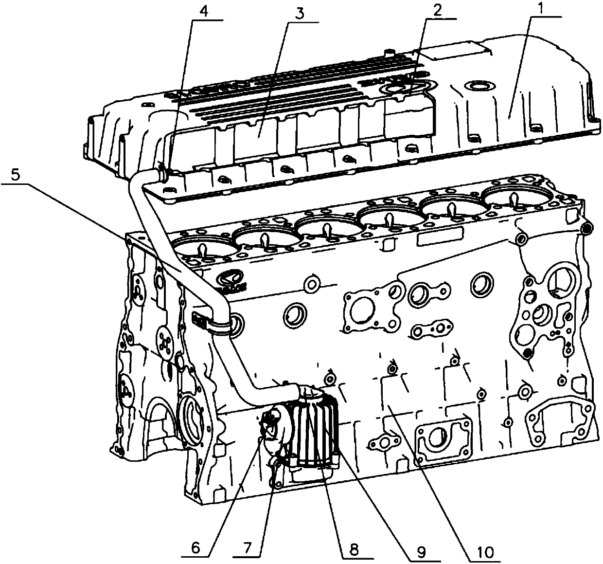
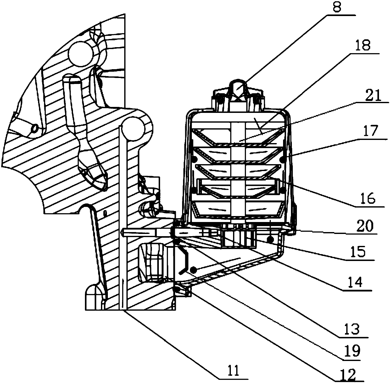
[0026] The core of the invention is to provide an engine oil-gas separator, which can improve the separation efficiency and reduce the use cost. Another core of the present invention is to provide an engine comprising the above-mentioned engine oil-gas separator, which can improve the separation efficiency and reduce the use cost.

[0027] Please refer to figure 1 with figure 2 , figure 1 It is a structural diagram of a specific embodiment of the engine oi...


PUM


Abstract

The invention discloses an engine oil-gas separator. The engine oil-gas separator comprises a separator body, a cylinder block oil inlet channel and an engine oil pump, wherein the separator body comprises a cover shell fixedly connected to a cylinder block, a rotary shaft arranged in the cover shell, blades arranged on the rotary shaft and a driving rotor connected to the rotary shaft; the rotaryshaft is vertically arranged; the top of the cover shell is provided with a separator inlet, and the bottom of the cover shell is provided with a separator oil outlet; the side portion of the cover shell is provided with a separator gas outlet; the cylinder block oil inlet channel is formed in the cylinder block, and an outlet of the cylinder block oil inlet channel is aligned with the driving rotor; the engine oil pump is used for delivery engine oil and can deliver engine oil in the cylinder block oil inlet channel, so that the engine oil is sprayed to the driving rotor to drive the drivingrotor. In the engine oil-gas separator, the engine oil is sprayed to the driving rotor to make the blades rotate; oil and gas are separated through the centrifugal separation principle, the separation efficiency can be guaranteed, and the usage cost of users can be reduced. The invention further discloses an engine comprising the engine oil-gas separator. The separation efficiency can be improved. The usage cost can be reduced.

Description

technical field [0001] The invention relates to the technical field of engines, in particular to an engine oil-gas separator. In addition, the present invention also relates to an engine comprising the above-mentioned engine oil-gas separator. Background technique [0002] With the deteriorating air quality, the topic of vehicle emissions has been pushed to the forefront, and the emission regulations formulated by the country are becoming more and more stringent. In order to meet the requirements of emission regulations, each engine manufacturer needs to use the latest technology and design to improve engine emissions. [0003] In the existing engine oil-gas separator, it is necessary to use the filter element for separation and filtration. As time goes by, the accumulation of dirt on the filter element will seriously reduce the separation efficiency, and the filter element needs to be replaced in time. The efficiency and economy are not very ideal. [0004] Therefore, how...

Claims


Application Information

Patent Timeline
Patent Type & Authority Applications(China)
IPC IPC(8): F01M13/04
CPCF01M13/04F01M2013/0422
Inventor 张猛王福冬刘世峰汪承红张莉
Owner ANHUI HUALING AUTOMOBILE
Why Eureka
Try Eureka