
Valve connector for medical lines

A technology of connectors and valves, which can be applied to other medical devices, valves, connecting pipes, etc., and can solve problems such as cost increase

Active Publication Date: 2018-03-27
IND BORLA
View PDF14 Cites 4 Cited by
  • Summary
  • Abstract
  • Description
  • Claims
  • Application Information

AI Technical Summary

Problems solved by technology

This confinement ring ensures a hermetic seal of the connector in its operating state, even in situations where high pressures are generated in the connector: however, the presence of the confinement ring poses some challenges during mechanized connector manufacturing and assembly and complexity, and thus cost

Method used


Image

  • Valve connector for medical lines
  • Valve connector for medical lines
  • Valve connector for medical lines

Examples


Embodiment Construction

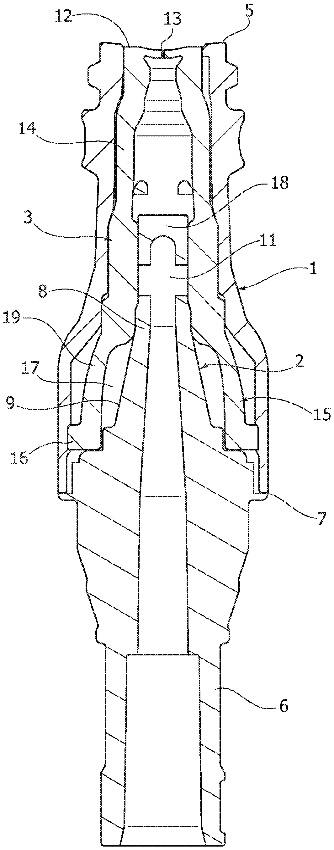
[0019] figure 1 A cross-sectional view of a valve connector according to the aforementioned prior art document EP 2123322 A1 is shown. It consists essentially of four parts: an outer tubular body 1 ; an inner hollow prong 2 arranged coaxially in the cavity of the tubular body 1 ; an elastic sealing member, indicated in its entirety by reference number 3 ; and an annular member 4 . Typically, the tubular body 1 , the hollow prong 2 and the ring 4 are made of a rigid plastic material, while the sealing member 3 is made of an elastic material, for example silicone rubber.

[0020] The tubular body 1 has an inlet end 5 shaped to form a female Luer lock connection member for engaging in a conventional manner with a male Luer lock connection member of a fluid introducer such as Consists of a needle-free syringe.

[0021] The hollow prong 2 has a base portion 6 shaped to form a male luer lock connection member or of any other type which is permanently joined at 7 to the end of the...


PUM


Abstract

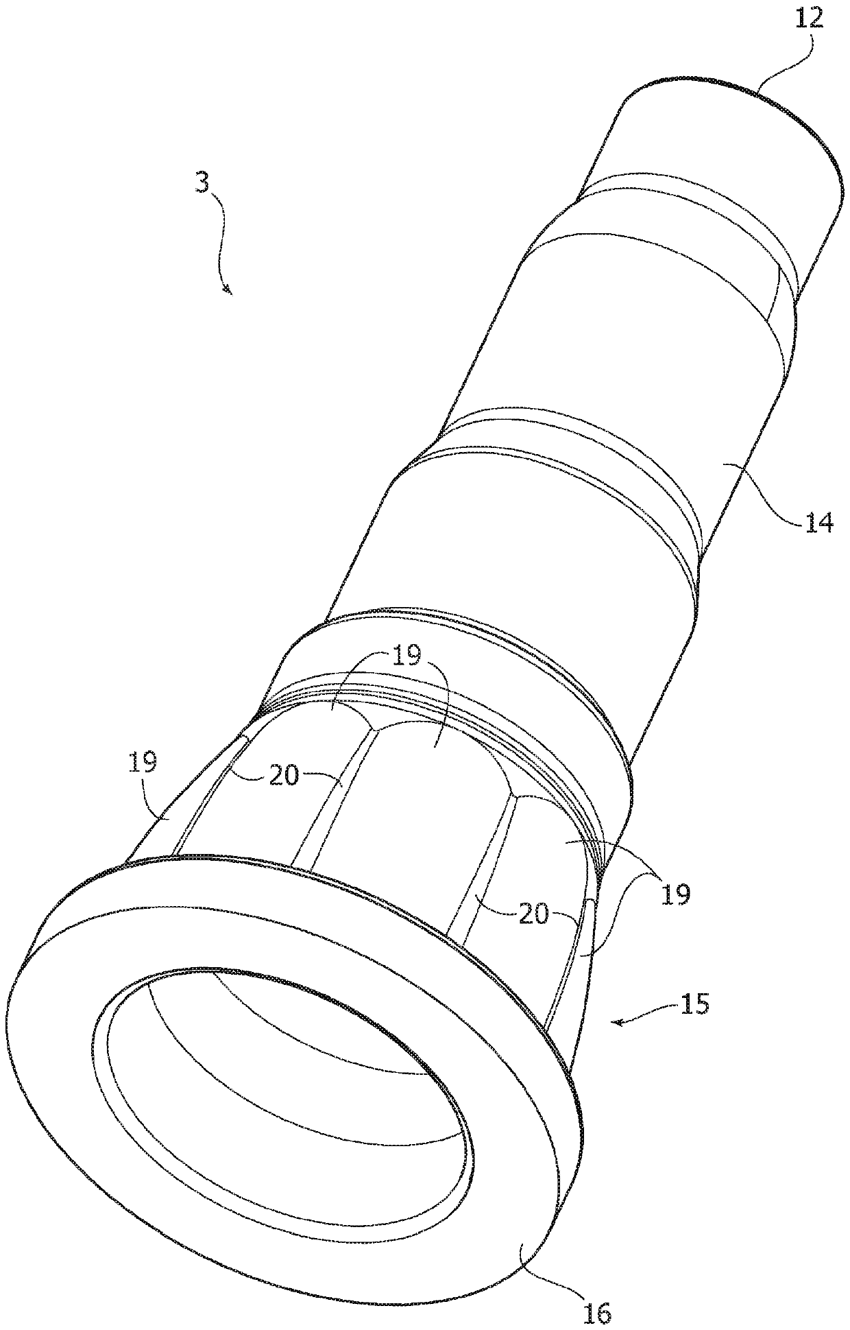
Valve connector for infusion medical lines comprising an outer tubular body (1), an inner hollow spike (2) and an intermediate sealing member formed by an elastic hollow element (3) including a head (12) with a pre-slit (13) normally closed. The elastic hollow element (3) has a base part (15) substantially generally barrel-shaped and a wall having a differentiated radial thickness (19, 20).

Description

technical field [0001] The present invention relates to valve connectors for medical lines such as injection lines by means of fluid substance introducers, usually made of luer connectors or luer locks such as needle-free syringes . Background technique [0002] Document EP-1834665A1 by the same applicant discloses a valve connector according to the preamble of claim 1, said valve connector comprising a tubular body having an inlet end and an outlet end arranged to engage fluid guide. A hollow prong is arranged axially in the cavity of the tubular body, said hollow prong having a closed tip facing the inlet end of the tubular body, while it also communicates with the outlet end of the tubular body. The connector also includes an elastic sealing member formed by an elastic hollow element sandwiched between the tubular body and the hollow prong, and the elastic hollow element has an elastic head provided with a pre-slit, and the elastic head is generally A closed state is a...

Claims


Application Information

Patent Timeline
Patent Type & Authority Applications(China)
IPC IPC(8): A61M39/26
CPCA61M2039/1033A61M2039/267A61M39/26A61M39/10A61M2039/1077A61M39/045
Inventor G.古亚拉
Owner IND BORLA
Learn More