
Fuel cell and fuel cell stack

A fuel cell stack and membrane electrode technology, applied in fuel cells, circuits, electrical components, etc., can solve problems such as suboptimal volume power density, non-uniform distribution of reactants, slow dynamic response, etc., to achieve good fuel cell efficiency, Good uniform distribution and low pressure loss

Active Publication Date: 2018-03-27
VOLKSWAGEN AG +1
View PDF8 Cites 6 Cited by
  • Summary
  • Abstract
  • Description
  • Claims
  • Application Information

AI Technical Summary

Problems solved by technology

[0008] The described bipolar plates and fuel cells have the disadvantage that due to the arrangement of the porous flow bodies, although the volume of the fuel cell is reduced compared to profiling bipolar plates, the volumetric power density is not yet optimal
Furthermore, the use of porous flow bodies also leads to slow dynamic response compared to conventional flow fields constructed by flow channels, leading to increased pressure loss on both gas sides, leading to poor drainage and to non-uniform distribution of reactants in the Both sides of the membrane electrode unit

Method used


Image

  • Fuel cell and fuel cell stack
  • Fuel cell and fuel cell stack
  • Fuel cell and fuel cell stack

Examples


Embodiment Construction

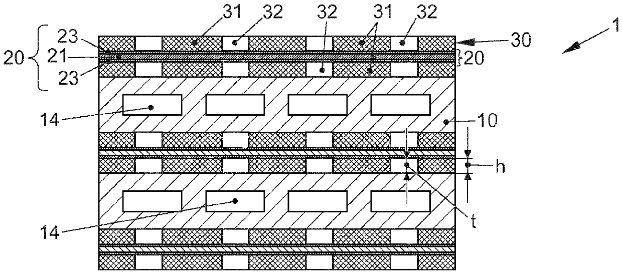
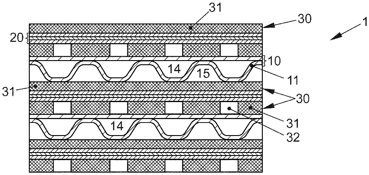
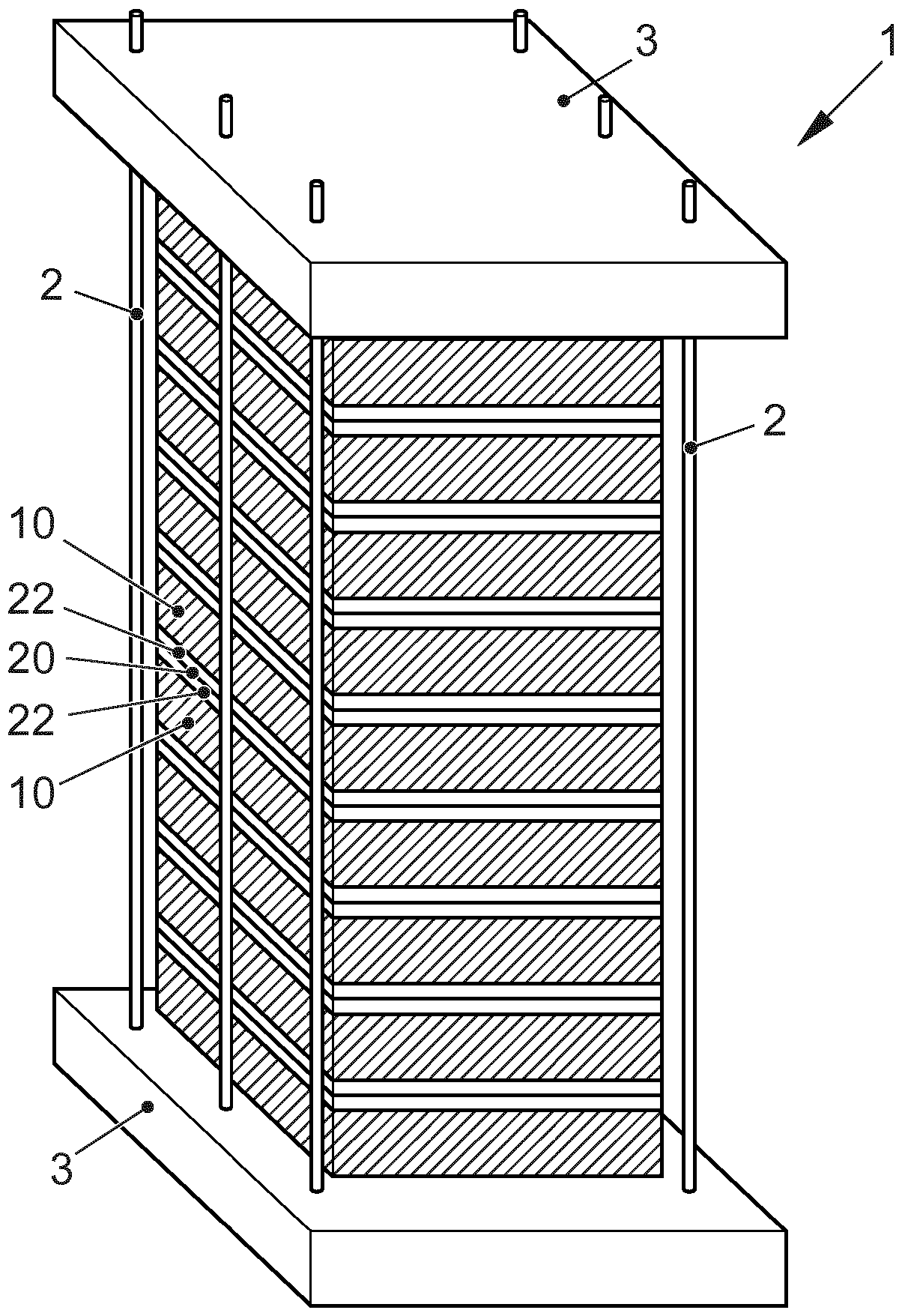
[0042] figure 1 A fuel cell stack is shown in a strongly schematic illustration. The fuel cell stack 1 comprises two end plates 3 between which a plurality of stacked stack elements comprising bipolar plates 10 and membrane electrode units 20 are arranged. The bipolar plates 10 are alternately stacked with the membrane electrode units 20 . The membrane electrode unit 20 includes a membrane and electrodes connected on both sides of the membrane, ie, an anode and a cathode (not shown), respectively. In addition, the membrane electrode unit 20 can have a gas diffusion layer 22 abutting the electrodes. A sealing element is arranged between the bipolar plate 10 and the membrane electrode unit 20 , which seals the anode chamber and the cathode chamber gas-tight to the outside (not shown). The fuel cell stack 1 is pressed together between the end plates 3 by means of tensioning elements 2 , for example tie rods or clamping plates.

[0043] exist figure 1 In , only the narrow sid...


PUM

PropertyMeasurementUnit
pore sizeaaaaaaaaaa

Abstract

The invention relates to a fuel cell stack (1), comprising: bipolar plates (10) each having an active region (13a), wherein a surface of the bipolar plate is of non-profiled form at least in the active region (13a), a membrane-electrode unit (20) arranged between in each case two bipolar plates (10), and a gas distributor layer (30) arranged between the membrane-electrode unit (20) and one of thebipolar plates (10), wherein the gas distributor layer (30) comprises a porous flow body (31). It is provided that the gas distributor layer (30) has recesses (32) in the active region (13a).

Description

technical field [0001] The invention relates to a fuel cell stack comprising a plurality of bipolar plates each having an active area, wherein the surfaces of the bipolar plates are designed so that they are not profiled at least in the active area ; a membrane electrode unit arranged between two bipolar plates; and a gas distribution layer arranged between the membrane electrode unit and at least one of the bipolar plates, wherein the gas distribution layer comprises a porous fluid body (Flusskörper ). Background technique [0002] Fuel cells utilize the electrochemical conversion of fuel and oxygen into water to generate electricity. For this purpose, the fuel cell contains a so-called membrane electrode unit (MEA, for membrane electrode assembly) as a core component, which is composed of an ion-conducting, in particular proton-conducting membrane and a membrane arranged on both sides of the membrane. A complex of electrodes (anode and cathode). Furthermore, the gas dif...

Claims


Application Information

Patent Timeline
Patent Type & Authority Applications(China)
IPC IPC(8): H01M8/1004H01M8/1018H01M8/0232H01M8/0258
CPCH01M8/0232H01M8/0258H01M8/1004H01M8/1018Y02E60/50H01M8/241H01M2008/1095
Inventor H.肖尔茨
Owner VOLKSWAGEN AG
Learn More