A combination rolling machine
A technology of a plate rolling machine and a frame, which is applied in the field of sheet metal processing, can solve problems such as inconvenience in work and burns, and achieve the effects of facilitating the reclaiming work, increasing the cooling speed, and increasing the contact area.
- Summary
- Abstract
- Description
- Claims
- Application Information
AI Technical Summary
Problems solved by technology
Method used
Image
Examples
Embodiment 1
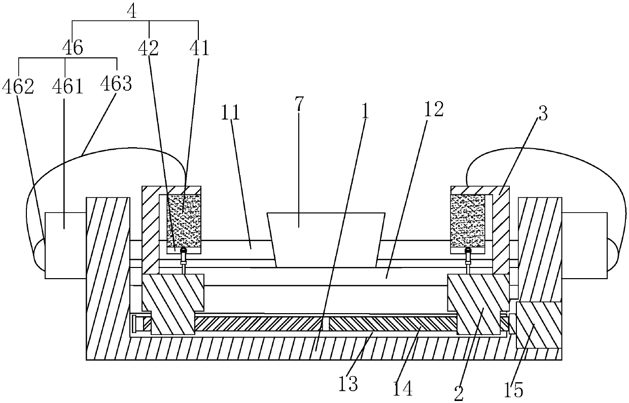
[0032] Embodiment 1: a kind of combination bending machine, such as figure 1 As shown, it includes the frame 1, the upper roller, the lower roller 12 and the transmission source (not shown in the figure), etc., the upper roller is the main transmission roller, connected with the power source, and the lower roller 12 moves vertically to clamp the plate. Through the rotation of the upper roller 11, the process of curling the plate can be realized.
[0033] Such as figure 1 As shown, at this time, a guide rail 13 parallel to the upper roller 11 is provided on the frame 1, and a working screw 14 connected with the drive motor 15 is arranged in the guide rail 13. The two ends of the working screw 14 are respectively provided with left-handed threads and right-handed threads. screw thread, that is, the working screw 14 is a double-helix screw, and the two ends of the working screw 14 are screwed with a slider 2, and the working screw 14 rotates under the work of the drive motor 15,...
specific Embodiment approach
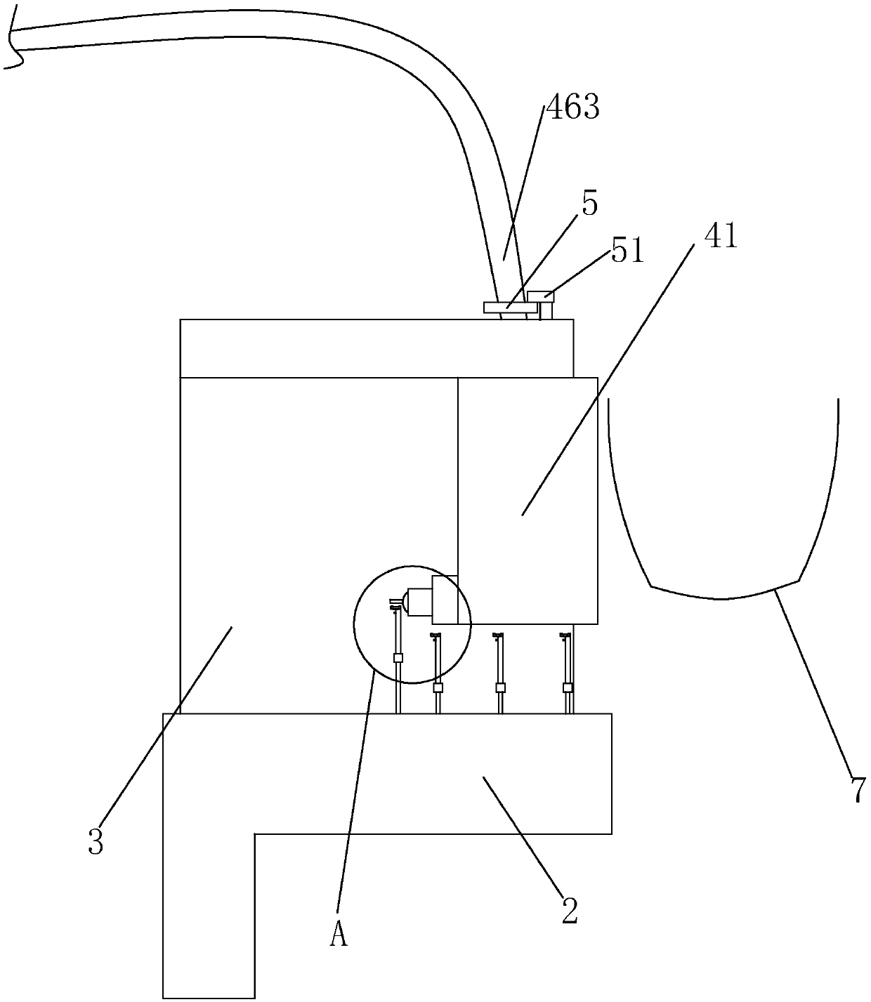
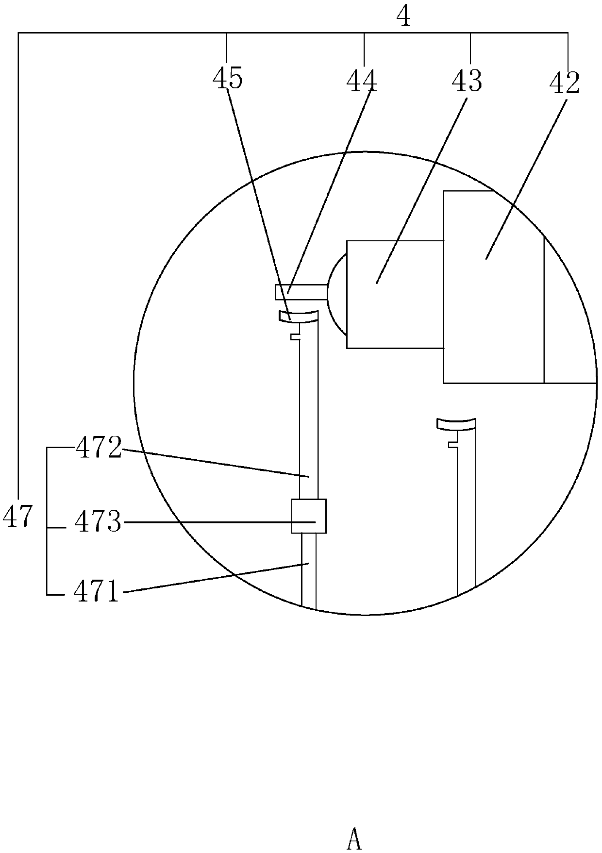
[0035]Specific implementation method: after the coiling plate 7 finishes the processing work, the drive motor 15 works, the working screw 14 rotates, and the two sliders 2 move towards each other to the position close to the coiling plate 7 at the same time, during this process, the water pump 462 works to control the water storage tank The water liquid in 461 enters in the outlet pipe 463, and flows into the sponge pad 41 to soak the sponge pad 41. When the slider 2 drives the sponge pad 41 close to the coil 7, the soaked sponge pad 41 can be connected to the coil 7. The outer surface is in contact, and the water liquid in the sponge pad 41 contacts the coiled plate 7 to realize the heat absorption work to the coiled plate 7; in this process, because the sponge pad 41 has good elasticity and deformation performance, it can The curling degree of this batch of coiled plates 7 is adjusted to the shape of the sponge pad 41, so that the shape of the sponge pad 41 fits the curved sh...
Embodiment 2
[0039] Embodiment 2: A combined plate bending machine, the difference from Embodiment 1 is that, as Figure 5 and 6 As shown, at this time, a connecting plate 31 arranged parallel to the slider 2 is hinged at the top of the support frame 3 near the sponge pad 41, and a piece of connecting plate 31 perpendicular to the connecting plate 31 is embedded in a sliding buckle on the lower surface of the connecting plate 31. Heat dissipation plate 32, heat dissipation plate 32 realizes the sliding connection on connection plate 31 by moving fast, and also is provided with sponge pad 41 on the side of heat dissipation plate 32 close to support frame 3, and also is provided with control heat radiation on connection plate 31 The position limiting mechanism 33 of the plate 32 is fixed.
[0040] Such as Figure 6 As shown, the limit mechanism 33 includes a plurality of sets of limit grooves 332 arranged on the connecting plate 31 and arranged in an array along the length direction of the...
PUM
 Abstract
Description
Claims
Application Information
 - R&D
- Intellectual Property
- Life Sciences
- Materials
- Tech Scout
- Unparalleled Data Quality
- Higher Quality Content
- 60% Fewer Hallucinations
Browse by: Latest US Patents, China's latest patents, Technical Efficacy Thesaurus, Application Domain, Technology Topic, Popular Technical Reports.
© 2025 PatSnap. All rights reserved.Legal|Privacy policy|Modern Slavery Act Transparency Statement|Sitemap|About US| Contact US: help@patsnap.com


