Truck special for containers and used for loading and unloading shared bicycles
A technology for sharing bicycles and containers, applied in the field of trucks, can solve the problems of wasting human resources, parking shared bicycles everywhere, and low work efficiency, and achieve the effect of saving labor costs and time costs.
- Summary
- Abstract
- Description
- Claims
- Application Information
AI Technical Summary
Problems solved by technology
Method used
Image

Examples
Embodiment 1
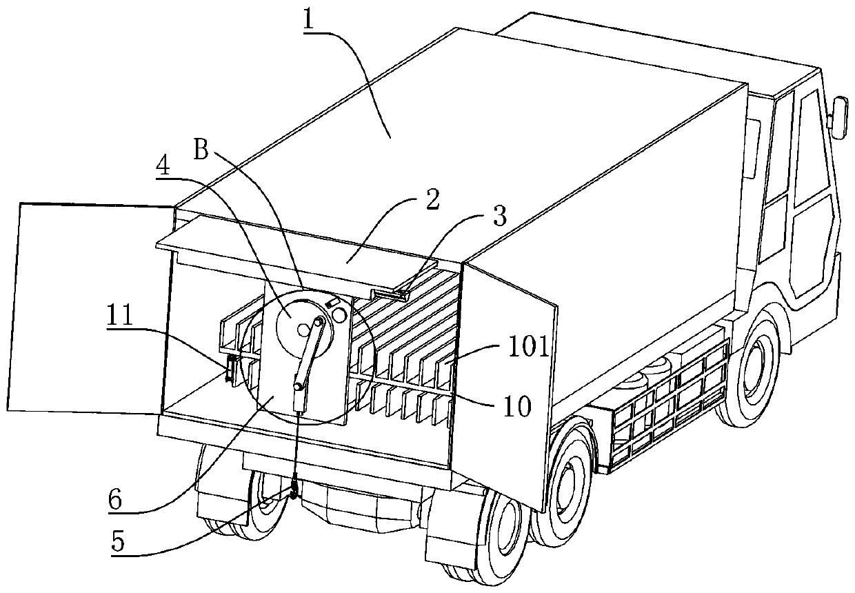
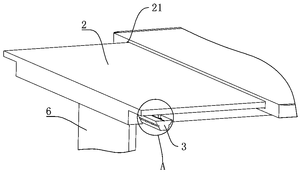
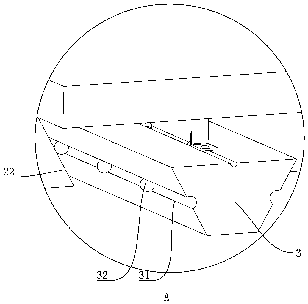
[0020] A special container truck for loading and unloading shared bicycles, such as Figure 1-3 As shown, this special-purpose truck comprises compartment 1, and compartment 1 comprises top plate, bottom plate and car door, and the top plate rear end (door place) of compartment 1 is provided with chute-21 along its length direction, and the sliding fit in chute-21 is provided with drawer. Pull plate 2, the pull plate 2 is provided with a chute 22 along the width direction of the compartment 1 at one end of the door, and a moving rod 3 is slid inside the chute 22. According to the position of the vehicle on the ground, the pull plate 2 can be slid outwards. Adjust the front and rear positions, and then horizontally adjust the left and right positions of the moving rod 3, so that the hook 5 below the moving rod 3 is in the best position. 5 Move upwards, and then lift the bicycle to the floor of compartment 1, put it into compartment 1 with the assistance of the staff, and move t...
Embodiment 2
[0022] The difference between this embodiment and embodiment 1 is: as Figure 4 As shown, the elevating mechanism 4 is a crank slider mechanism, the bottom end of the moving rod 3 is fixed with a vertical suspension plate 6, the crank slider mechanism is fixed on the suspension plate 6, and the crank slider mechanism includes a crank 41 and a hook 5 The connected slide block 42 and the crank 41 move circularly under the drive of the motor (not shown in the figure), and the slide block 42 converts the circular motion of the crank 41 into up and down movement, and then drives the hook 5 up and down.
Embodiment 3
[0024] The difference between this embodiment and embodiment 2 is: as Figure 4 As shown, a position sensor 7 is fixed on the outer edge of the crank 41 on the suspension plate 6, a magnetic block 8 for sensing signals is fixed on the circumferential surface of the crank 41, and the position sensor 7 is electrically connected to a counter 9 and a power supply (not shown in the figure) ), when the magnetic block 8 rotates to the corresponding position of the position sensor 7, the position sensor 7 detects the signal and transmits the detection signal to the counter 9, the whole system is powered by the power supply, and the crank 41 rotates once, driving the hook 5 to perform a lift , the counter 9 accumulates once, which is convenient for counting the number of shared bicycles loaded and unloaded, and avoids overloading.
PUM
 Abstract
Description
Claims
Application Information
 - R&D
- Intellectual Property
- Life Sciences
- Materials
- Tech Scout
- Unparalleled Data Quality
- Higher Quality Content
- 60% Fewer Hallucinations
Browse by: Latest US Patents, China's latest patents, Technical Efficacy Thesaurus, Application Domain, Technology Topic, Popular Technical Reports.
© 2025 PatSnap. All rights reserved.Legal|Privacy policy|Modern Slavery Act Transparency Statement|Sitemap|About US| Contact US: help@patsnap.com