Braking mechanism and transportation vehicle

A braking mechanism and vehicle technology, applied in bicycle accessories, bicycle brakes, etc., can solve the problem of inability to realize the linkage control of front and rear brakes.

Pending Publication Date: 2018-03-30
CHANGXING HUAYI ELECTROMECHANICAL
View PDF9 Cites 3 Cited by
  • Summary
  • Abstract
  • Description
  • Claims
  • Application Information

AI Technical Summary

Problems solved by technology

However, in these vehicles, one brake line can only control one brake device, and the front and rear brakes are controlled separately by the left and right brake handles of the steering handle, but the left and right brake handles cannot realize the linkage control of the front and rear brakes

Method used


Image

  • Braking mechanism and transportation vehicle
  • Braking mechanism and transportation vehicle
  • Braking mechanism and transportation vehicle

Examples


Embodiment 1

[0034] This embodiment provides a braking mechanism.

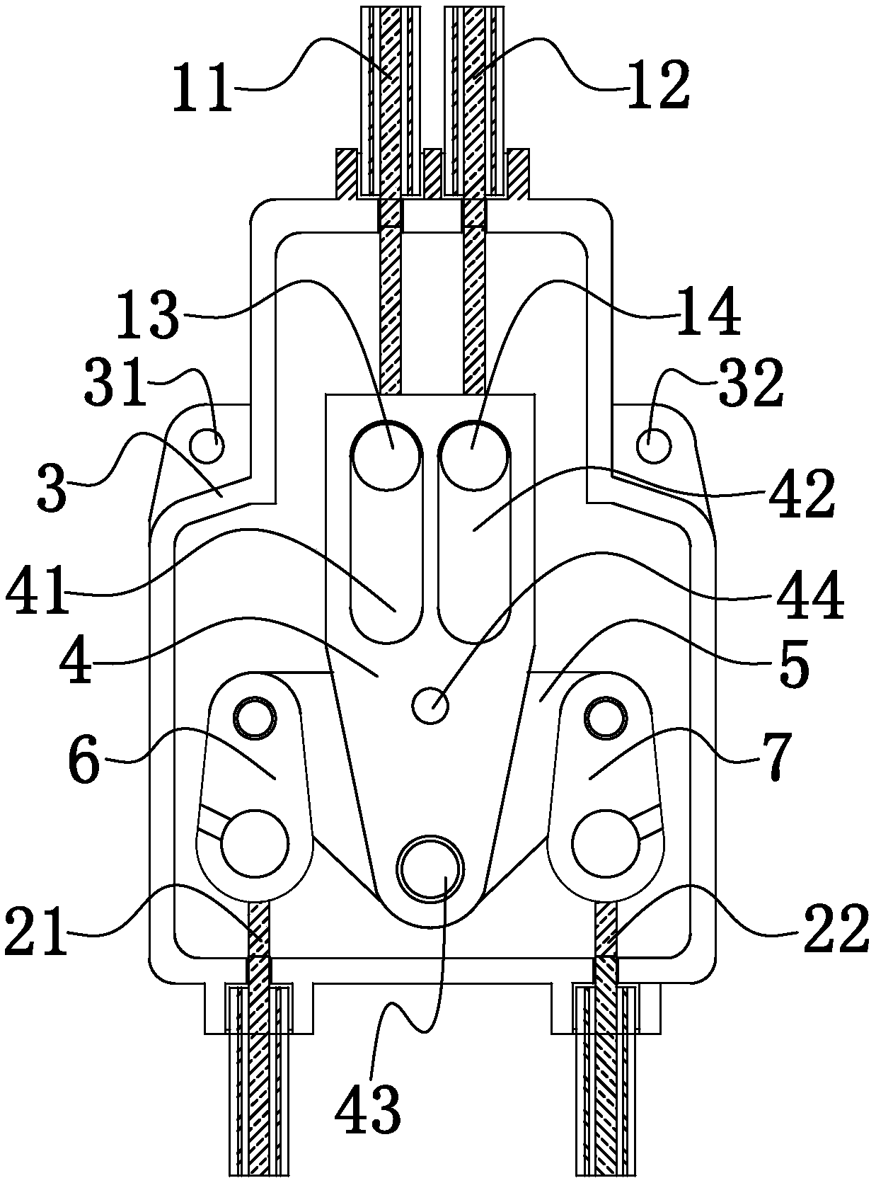
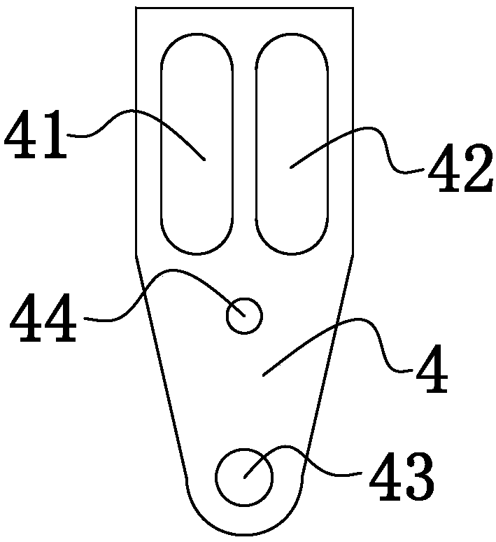
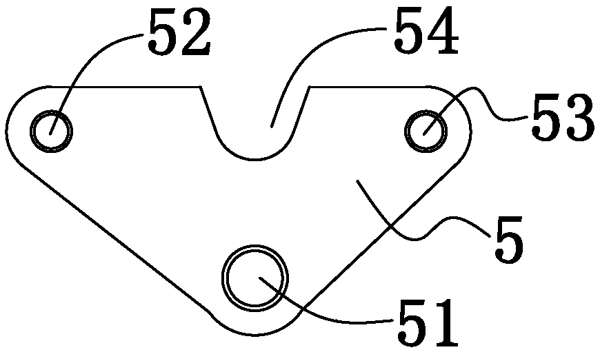
[0035] Such as figure 1 with Figure 4Shown, a kind of brake mechanism, comprises the left brake cable 11 that connects left brake lever, the right brake cable 12 that connects right brake lever, the front brake cable 21 that connects front brake and the rear brake cable 22 that connect rear brake, and brake mechanism also Including the brake control box 3, the brake control box 3 has a "convex" shape as a whole, and the left and right mounting holes 31 and 32 are respectively provided at the left and right sides of the brake control box in the shape of steps to fix the brake control box 3 at the installation location. The brake control box 3 is provided with a pull assembly, the pull assembly includes a pull piece 4 and a balance piece 5, the pull piece 4 is strip-shaped, and the lower end of the strip length direction is an isosceles triangle, the upper end is rectangular, and the short side of the rectangle is in line...

Embodiment 2

[0039] Such as Figure 5 As shown, this embodiment is a further improvement made on the first embodiment. The difference from Embodiment 1 is that the left brake cable is divided into a left pulling section 15 and a left driven section 16, the right brake cable is divided into a right pulling section 17 and a right driven section 18, and the left pulling section 15 and a left driven section 16 1. Between the right pulling section 17 and the right driven section 18, a cable connector 8 is respectively arranged, and the cable connector 8 includes a fixed seat 81 and a slider 82 arranged in the fixed seat 81, and the two ends of the slider 82 are respectively provided with stoppers. The plate, the slider 82 and the two baffles form a C shape, and the inner sides of the two baffles are respectively provided with a first slider 83 and a second slider 84 .

[0040] One end of the left pulling section 15 is connected to the left brake lever, the other end passes through the baffle a...

Embodiment 3

[0044] This embodiment provides a bicycle, which includes the braking mechanism described in Embodiment 1 or Embodiment 2.


PUM


Abstract

The invention discloses a braking mechanism and a transportation vehicle, and relates to the field of transportation tools. The braking mechanism includes a braking cable, a front gate line, a back gate line and a braking control box. The braking control box is internally provided with a pull assembly. The pulling assembly comprises a pulling part and a balancing part. The balancing part is rotationally connected to the pulling part. The braking cable pulls the pulling part so as to drive the balancing part to pull the front gate line and the back gate line simultaneously. The balancing part rotates to distribute the braking force of the front gate line and the back gate line. According to the braking mechanism, linkage control of one braking handle over a front gate and a back gate is achieved, and the braking force of the front gate line and the back gate line can be properly distributed.

Description

【Technical field】 [0001] The invention relates to the field of transportation tools, in particular to a braking mechanism and a transportation tool. 【Background technique】 [0002] At present, two-wheeled or three-wheeled means of transport including bicycles, electric vehicles, motorcycles, etc. have become the simplest and most practical means of transport that people use most in the world. But in these vehicles, one brake line can only control one brake device, and the front and rear brakes are controlled respectively by the left and right brake handles of the steering handle, but the left and right brake handles cannot realize the linkage control of the front and rear brakes. 【Content of invention】 [0003] In order to solve the aforementioned problems, the present invention provides a new type of brake mechanism, which realizes the linkage control of the front and rear brakes by a brake handle. [0004] In order to achieve the above object, the present invention adop...

Claims


Application Information

Patent Timeline
Patent Type & Authority Applications(China)
IPC IPC(8): B62L3/08B62L3/02
CPCB62L3/026B62L3/08
Inventor 许志明
Owner CHANGXING HUAYI ELECTROMECHANICAL
Why Eureka
Try Eureka