Lens cone, lens module and electronic equipment

A technology of electronic equipment and lens modules, applied in the direction of installation, optics, instruments, etc., to achieve the effect of improving consistency

Active Publication Date: 2018-03-30
GUANGDONG OPPO MOBILE TELECOMM CORP LTD
View PDF7 Cites 0 Cited by
  • Summary
  • Abstract
  • Description
  • Claims
  • Application Information

AI Technical Summary

Problems solved by technology

However, there is a height difference between the surface of the current lens barrel and the inner side of the light incident area, and this height difference is usually compensated by a slope or a stepped structure, resulting in the formation of obvious ridges on the outer surface of the lens barrel

Method used


Image

  • Lens cone, lens module and electronic equipment
  • Lens cone, lens module and electronic equipment
  • Lens cone, lens module and electronic equipment

Examples


no. 1 example

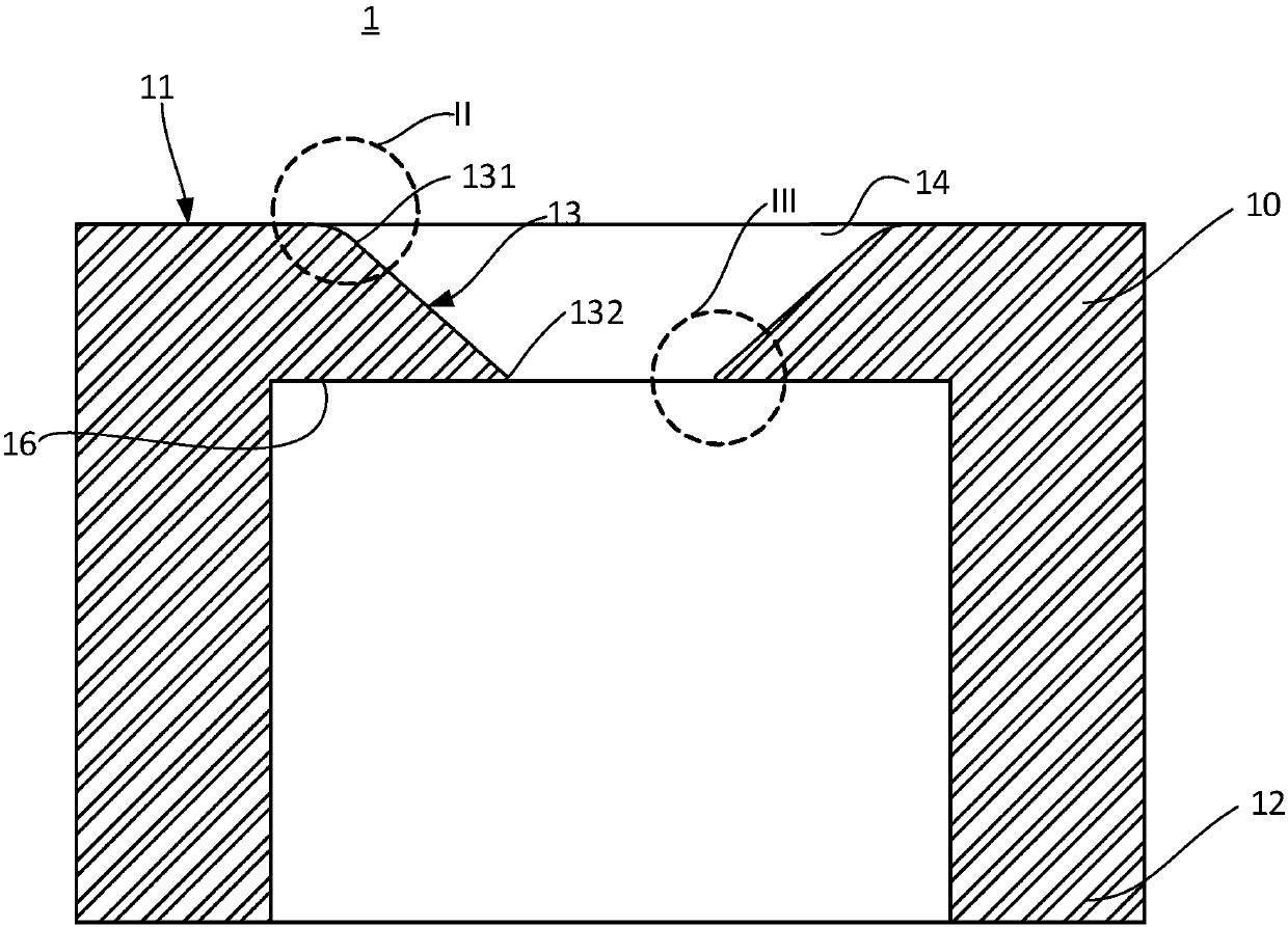
[0026] see Figure 1 to Figure 4 The lens barrel 1 provided in the first embodiment of the present application has a first end 10 and a second end 12 , and the first end 10 and the second end 12 are opposite ends of the lens barrel 1 .

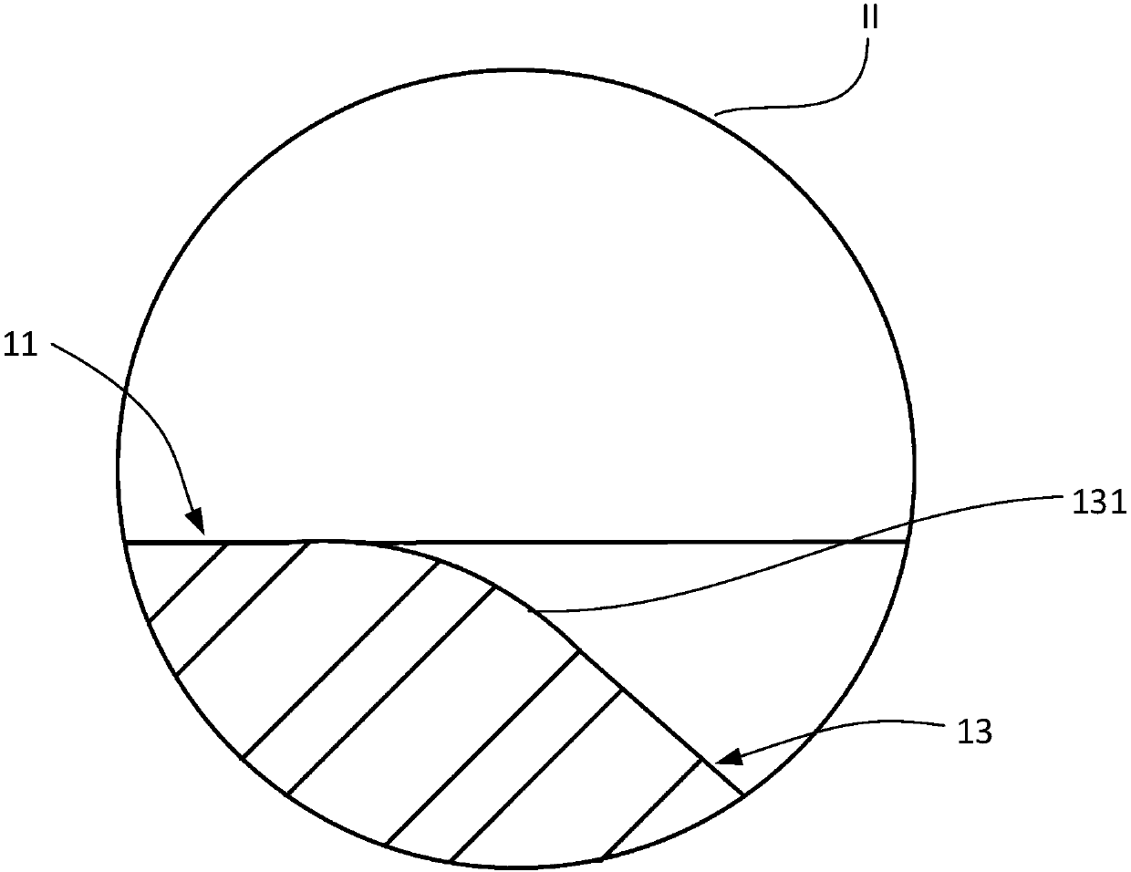
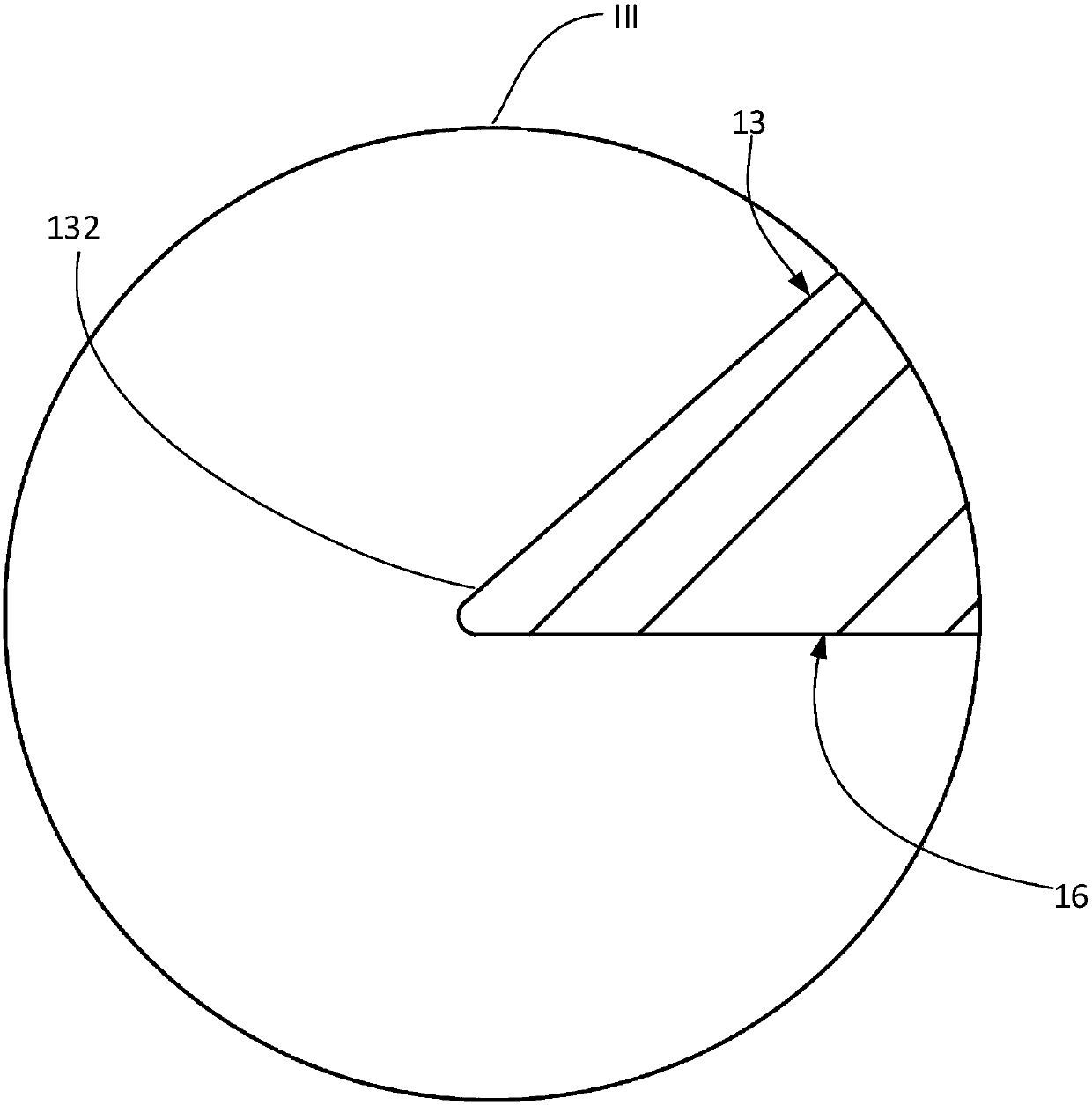
[0027] The first end portion 10 is provided with a light entrance hole 14 that communicates with the interior of the lens barrel 1. The first end portion 10 includes a first end surface 11 and an annular inner wall 13 connected to the first end surface 11. The annular inner wall 13 is arranged around the light entrance hole 14. . The light incident hole 14 is located at the center of the first end portion 10 .

[0028] The annular inner wall 13 can be regarded as formed by the first end surface 11 entering inwardly into the interior of the lens barrel 1 . The annular inner wall 13 has a first peripheral edge 131 and a second peripheral edge 132 , and the height difference between the first end surface 11 and the second peripheral edge 132 is...

no. 2 example

[0034] see Figure 5 , in this embodiment, a lens module 2 is provided, the lens module 2 includes the lens barrel 1 provided in the first embodiment, and the lens group 20 , the lens group 20 is located inside the lens barrel 1 . Lens set 20 includes one or more lenses.

[0035] The lens barrel 1 of the lens module 2 has a circular arc transition around the light entrance hole without corners or ridges, which greatly improves the consistency of the structure.

no. 3 example

[0037] see Image 6 with Figure 7 This embodiment provides an electronic device 3 , the electronic device 3 has a first surface 31 and a second surface 32 opposite to the first surface 31 , and the first surface 31 is provided with a display screen 30 . The electronic device 3 includes the lens module 2 provided in the second embodiment. The lens module 2 is located on the first surface 31 and can be used as a front camera.

[0038] In one embodiment, the lens module 2 can also be located on the second surface 32 to be used as a rear camera.

[0039] In another embodiment, the electronic device 3 may have a first lens module and a second lens module, the two lens modules and the lens module 2 have the same structure, and are located on the first surface 31 and the second surface 32 respectively. .

[0040] In the electronic device 3 equipped with the lens module 2, the lens module eliminates the ridges around the light entrance hole, and the lines are smooth and harmonious...


PUM


Abstract

The invention relates to a lens cone, which is provided with a first end part, wherein the first end part is provided with a light inlet hole communicated with internal part of the lens cone, the first end part comprises a first end surface and an annular inner wall connected with the first end surface, the annular inner wall is arranged around the light inlet hole, and the junction of the first end surface and the annular inner wall is a circular arc chamfer. The invention further provides a lens module comprising the lens cone and electronic equipment. The first end surface of the lens coneprovided by the embodiment of the invention is in circular arc connection with a first periphery of the annular inner wall, so that corner angles and ridges are enabled to be eliminated at the first periphery, and the consistency of structures such as the lens module applying the lens cone and the electronic equipment is greatly improved.

Description

technical field [0001] The present application relates to the field of camera technology, in particular to a lens barrel, lens module and electronic equipment. Background technique [0002] At present, the lens module includes a lens barrel and a lens group located in the lens barrel, combined with an image sensor, to form a camera module for capturing images. However, there is a height difference between the surface of the current lens barrel and the inner side of the light incident area, and this height difference is usually compensated by a slope or a stepped structure, resulting in the formation of obvious ridges on the outer surface of the lens barrel. Contents of the invention [0003] Embodiments of the present application provide a lens barrel, a lens module, and electronic equipment. [0004] In the first aspect, the embodiment of the present application provides a lens barrel, which has a first end portion, and the first end portion is provided with a light entr...

Claims


Application Information

Patent Timeline
IPC IPC(8): G02B7/02G02B7/00G03B30/00
CPCG02B7/00G02B7/021
Inventor 范奇文谭伟
Owner GUANGDONG OPPO MOBILE TELECOMM CORP LTD
Why Eureka
Try Eureka