
Transformer framework coiling device and method

A transformer skeleton and winding device technology, applied in the manufacture of inductors/transformers/magnets, electrical components, circuits, etc., can solve the problems of high working noise, no energy saving function, poor winding effect, etc. vibrating effect

Inactive Publication Date: 2018-03-30
惠州一诺精密电子有限公司
View PDF5 Cites 2 Cited by
  • Summary
  • Abstract
  • Description
  • Claims
  • Application Information

AI Technical Summary

Problems solved by technology

Now in the winding process, some still use manual winding, some use machine winding, and machine winding has disadvantages such as poor winding effect, excessive working noise, and no energy-saving function. have a certain impact in actual use

Method used


Image

  • Transformer framework coiling device and method
  • Transformer framework coiling device and method

Examples


Embodiment Construction

[0022] The following will clearly and completely describe the technical solutions in the embodiments of the present invention with reference to the accompanying drawings in the embodiments of the present invention. Obviously, the described embodiments are only some, not all, embodiments of the present invention.

[0023] In describing the present invention, it should be understood that the terms "upper", "lower", "front", "rear", "left", "right", "top", "bottom", "inner", " The orientation or positional relationship indicated by "outside", etc. is based on the orientation or positional relationship shown in the drawings, and is only for the convenience of describing the present invention and simplifying the description, rather than indicating or implying that the referred device or element must have a specific orientation, so as to Specific orientation configurations and operations, therefore, are not to be construed as limitations on the invention.

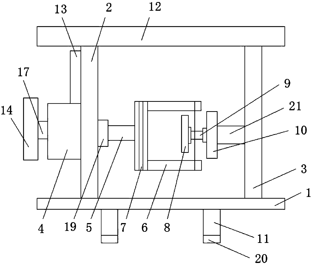
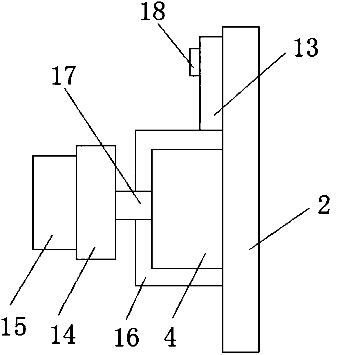
[0024] see Figure 1-2 ,...


PUM


Abstract

The invention discloses a transformer framework coiling device and a transformer framework coiling method. The transformer framework coiling device comprises a bottom plate; the outer wall at the toppart of the bottom plate is fixedly connected with a first supporting plate and a second supporting plate; the outer wall at one side of the first supporting plate is fixedly connected with a drivingmotor, and one end of the driving motor closing to the first supporting plate is moveably connected with a flexible rod; one end of the flexible rod far from the driving motor is fixedly connected with a coiling frame, the outer surface of one side of the coiling frame closing to the flexible rod is provided with a wire slot; the inner part of the coiling frame is provided with a first magnet, andthe outer wall at one side of the first magnet far from the coiling frame is fixedly and moveably connected with the transformer framework. Through the cooperative use of the driving motor, the coiling frame, the first magnet and the second magnet, the automatic coiling purpose can be realized; an anti-dust plate can prevent dust; a damping cushion arranged at the supporting foot can effectivelyreduce shock and protect the device.

Description

technical field [0001] The invention relates to the technical field of transformer skeletons, in particular to a transformer skeleton winding device and method. Background technique [0002] Transformers are inevitable components used in the manufacture of electronic equipment. The transformer skeleton, also known as the transformer wire frame, is the main structural component of the transformer. Transformers are widely used in today's society, and the corresponding main body is also indispensable, so the skeleton plays an irreplaceable role. Copper wires are wound on the transformer frame, and the difference between different types of transformers lies in the number of copper wires wound. In the production and manufacture of transformers, winding wires on the frame becomes a technical point. Now in the winding process, some still use manual winding, some use machine winding, and machine winding has disadvantages such as poor winding effect, excessive working noise, and no ...

Claims


Application Information

Patent Timeline
Patent Type & Authority Applications(China)
IPC IPC(8): H01F41/066H01F41/098
CPCH01F41/066H01F41/098
Inventor 杨海波杨励张海洲
Owner 惠州一诺精密电子有限公司
Learn More