Supercharge Your Innovation With Domain-Expert AI Agents!

Thickness experimental device and application method thereof for variable boundary layer during cavity flow wind tunnel test research

A technology of boundary layer thickness and wind tunnel test, applied in the field of experimental fluid mechanics, it can solve the problems of large change of boundary layer parameters, increase of boundary layer, not well solved, etc.

Inactive Publication Date: 2018-04-03
INST OF HIGH SPEED AERODYNAMICS OF CHINA AERODYNAMICS RES & DEV CENT
View PDF4 Cites 0 Cited by
  • Summary
  • Abstract
  • Description
  • Claims
  • Application Information

AI Technical Summary

Problems solved by technology

However, the method of Yang Dangguo et al. needs to prepare two sets of wind tunnel models during the implementation process, and the cost is relatively high.
Secondly, because the boundary layer of the side wall of the wind tunnel is much higher than the boundary layer of the core flow plate, the boundary layer parameters change too much, and it is difficult to effectively evaluate the intermediate change process
In the method proposed by Plentovich et al., it is necessary to stick corundum covering about 2 / 3 of the area of ​​the plate to achieve a significant change in the thickness of the boundary layer, and the remaining 1 / 3 of the plate is used to restore the disturbed boundary layer. The sticking area has reached its limit, but the boundary layer thickness has only increased by 45%
The boundary layer gettering adopted by Illy et al. can only compare the two states before and after the gettering, and it is difficult to carry out a more systematic research on the continuous change of the boundary layer thickness.
In addition, changing the thickness of the boundary layer by changing the length of the plate is the easiest solution to think of, but theoretical analysis shows that increasing the size of the plate from 200mm to 400mm only increases the thickness of the boundary layer from 3.9mm to 6.8mm, but increases the weight of the model and will result in a significant decrease in model stiffness
In addition, Thangamani, when changing the size of the model, and Reynolds number have changed, and the influence of the two is difficult to distinguish when analyzing the results
[0006] Therefore, based on the research status at home and abroad, the problem of how to achieve continuous and significant changes in the thickness of the boundary layer of incoming flow has not been well resolved in the wind tunnel test of cavity flow.

Method used


Image

  • Thickness experimental device and application method thereof for variable boundary layer during cavity flow wind tunnel test research
  • Thickness experimental device and application method thereof for variable boundary layer during cavity flow wind tunnel test research
  • Thickness experimental device and application method thereof for variable boundary layer during cavity flow wind tunnel test research

Examples


Embodiment

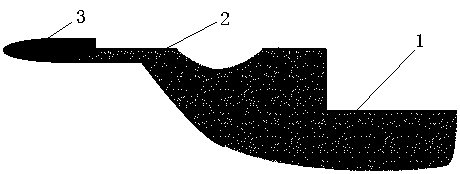
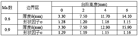
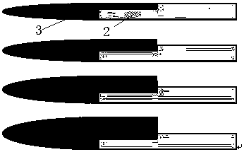
[0030] The test model is a C201 cavity standard mold with a total length of 514mm and a width of 320mm. Among them, the cavity is 200mm long, 66.7mm wide and 33.3mm deep. Before the cavity, there is a flat plate with a length of about 200 mm for the development of a turbulent boundary layer. In the experiment, step blocks of four different specifications such as 0mm, 2mm, 4mm, and 6mm were added to the front of the plate to change the thickness of the turbulent boundary layer at the entrance of the cavity, so as to study the influence of the boundary layer thickness on the unsteady flow of the cavity.

[0031] According to the characteristics of the back-step flow, the velocity profile of the flow in the separation zone and the recovery zone downstream of the step is an irregular velocity profile. In order to fully develop the flow in the boundary layer, it is necessary to set a sufficiently long recovery zone. The length of the recovery area is about 20 times the height of t...


PUM


Abstract

The invention provides a thickness experimental device and an application method thereof for a variable boundary layer during the cavity flow wind tunnel test research. The device comprises a cavity and a flat plate which are connected with each other. A recovery area and step blocks are arranged on the flat plate. The step blocks are located at the front end of the flat plate. The recovery area is a flat plate area between the step blocks and the cavity. According to the technical scheme of the invention, the step blocks with different thicknesses are additionally arranged on the flat plate on the front edge of the cavity, so that the continuous change of the thickness of a boundary layer at the inlet of the cavity is realized. Meanwhile, the maximum thickness of the boundary layer can reach four times that of the boundary layer in the basic state (before the additional arrangement of the step blocks).

Description

technical field [0001] The invention relates to experimental fluid mechanics, in particular to a variable boundary layer thickness experimental device suitable for cavity flow wind tunnel test research and its application method. Background technique [0002] A cavity is a geometric shape with only one side open and the other closed, such as a rectangular cavity, a cylindrical cavity, and the like. Due to the large storage space inside the cavity, this configuration is more commonly used in transportation vehicles, such as the carriages of large trucks and freight trains, the landing gear compartment of passenger aircraft, and the embedded bomb bay of fighter jets. In order to ensure the safety of the load, maintain a streamlined shape, and reduce driving resistance, the storage room is often closed. Only when large trucks and freight trains are empty, the landing gear of a passenger plane is opened during take-off and landing, and a fighter jet launches a built-in weapon, ...

Claims


Application Information

Patent Timeline
Patent Type & Authority Applications(China)
IPC IPC(8): G01M9/00
CPCG01M9/00
Inventor 刘俊吴军强杨党国高荣钊郑晓东张征宇罗新福孙常新
Owner INST OF HIGH SPEED AERODYNAMICS OF CHINA AERODYNAMICS RES & DEV CENT
Features
  • R&D
  • Intellectual Property
  • Life Sciences
  • Materials
  • Tech Scout
  • Unparalleled Data Quality
  • Higher Quality Content
  • 60% Fewer Hallucinations
Learn More