Annular hollow offset-focus laser cladding device

A laser cladding and ring-shaped technology, applied in additive manufacturing, coating, metal material coating process, etc., can solve the problems of large duty cycle, large cladding layer roughness, poor surface smoothness of finished products, etc. The effect of reducing the area

Pending Publication Date: 2021-07-13
SUZHOU UNIV
View PDF4 Cites 2 Cited by
  • Summary
  • Abstract
  • Description
  • Claims
  • Application Information

AI Technical Summary

Problems solved by technology

[0014] 3) The powder particles are seriously insufficiently heated, even without melting, they are still solid particles,
[0016] At the same time, the conventional laser cladding rate is low, generally 0.5-3m/min, the powder utilization rate is low, generally about 60%, and the cladding layer is rough, resulting in serious waste of materials, and the laser energy is focused on the base material. The powder is mixed and combined by melting the matrix material, which makes the laser energy utilization efficiency and cladding rate low, and the energy absorbed by the powder center is not enough under the large defocus, so that the powder is still solid particles when combined with the matrix material, and the surface of the finished product is smooth. degree difference
In order to improve the cladding efficiency, by increasing the laser power and increasing the spot area, but it will lead to an increase i

Method used


Image

  • Annular hollow offset-focus laser cladding device
  • Annular hollow offset-focus laser cladding device
  • Annular hollow offset-focus laser cladding device

Examples


Embodiment 1

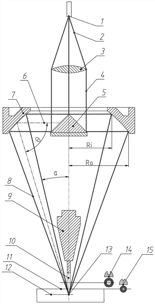
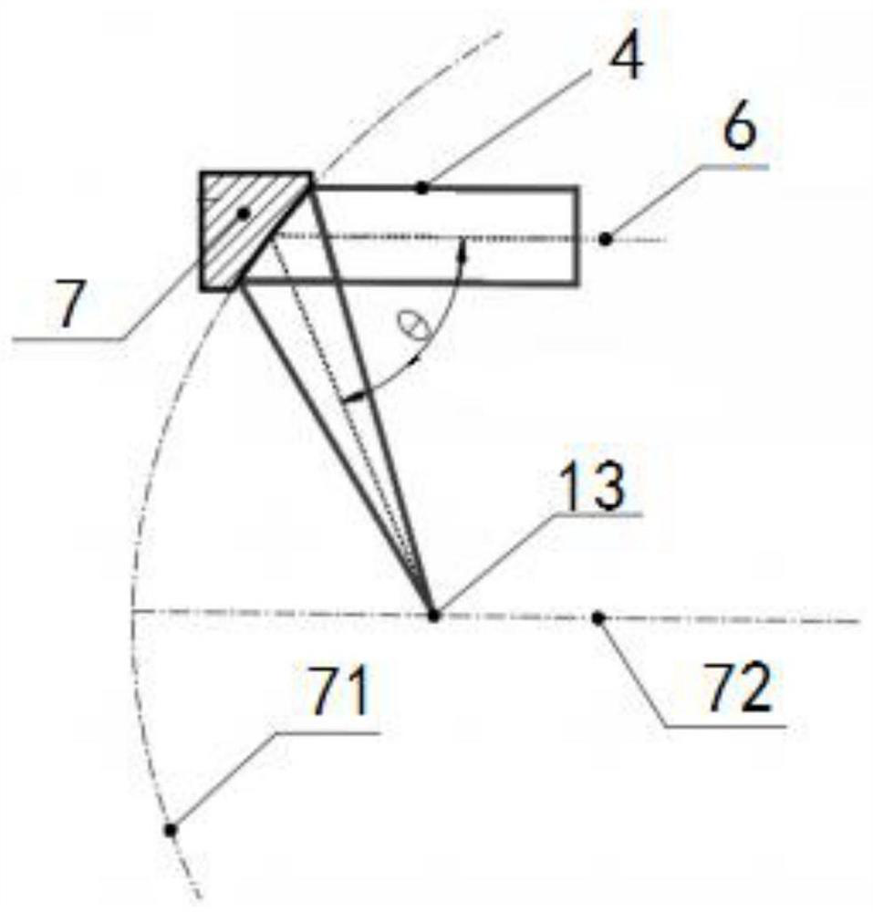
[0047] Such as Figure 3-6 As shown, this embodiment provides an annular hollow off-focus laser cladding device, including an upper cover plate 16, a housing 18, a composite mirror holder bracket 17, a conical mirror 5, an annular off-axis parabolic focusing mirror 7, a protective mirror 19, Jet base, protective gas cover 28 etc., housing 18 tops are provided with light entrance 29, and housing 18 is provided with conical reflector 5 (conical straight-face reflector can be adopted) facing light entrance 29, opposite and parallel with conical reflector 5. An annular off-axis parabolic focusing mirror 7 is arranged coaxially. Composite mirror base support 17 is installed in the shell 18, and the outer ring of composite mirror base support 17 is provided with the installation part of annular off-axis parabolic focusing mirror 7, and the middle part is provided with the installation part of conical reflector 5, and two installation parts can pass rib The plates are connected, and...


PUM


Abstract

The invention discloses an annular hollow offset-focus laser cladding device, and relates to the technical field of laser processing. The annular hollow offset-focus laser cladding device comprises a shell, a conical reflector, an annular off-axis parabolic focus lens, a nozzle and a powder spraying pipe, the top of the shell is provided with a light inlet, the conical reflector is arranged in the shell, and the conical reflector is arranged facing the light inlet; the annular off-axis parabolic focus lens and the conical reflector are oppositely and coaxially arranged; and the nozzle is installed below the conical reflector, the lower end of the nozzle is connected with the powder spraying pipe, the powder spraying pipe is coaxial with annular hollow offset-focus light formed after reflection of the annular off-axis parabolic focus lens, and a collimation protection gas sleeve is arranged on the periphery of the powder spraying pipe. The annular off-axis parabolic focus lens is used for horizontally shifting the focusing focus of the maternal parabola. According to the annular hollow offset-focus laser cladding device, the homogenization of the energy density of an annular light spot is realized, the coupling effect of a laser beam and powder is improved, the utilization rate of the metal powder is improved, and the cladding quality and appearance are improved.

Description

technical field [0001] The invention relates to the technical field of laser processing, in particular to an annular hollow defocused laser cladding device. Background technique [0002] Laser cladding technology is an advanced manufacturing technology combining laser technology and additive manufacturing technology, which has developed rapidly in recent years. As an advanced processing and forming technology, it is widely used in metal 3D printing, surface modification of materials and repair of failed parts, etc., which solves many problems in engineering practice and creates huge economic benefits in engineering applications. Laser cladding equipment mainly includes lasers, cladding nozzles, processing platforms and feeding devices. The laser cladding nozzle is the key core component of the laser cladding system, which can realize the transmission, transformation, focusing and synchronous delivery of the cladding material of the laser beam, and realize the precise coupli...

Claims


Application Information

Patent Timeline
IPC IPC(8): B22F12/00B22F10/28B22F12/41B22F12/44B22F12/53B22F10/36C23C24/10B33Y30/00B33Y40/00
CPCB22F3/003C23C24/103B33Y30/00B33Y40/00Y02P10/25B23K26/342B23K26/0643B23K26/0665B23K26/073B23K26/0734B23K26/144B23K26/1476B22F12/41B22F12/53B22F12/70B22F10/25B22F10/36G02B19/0028B23K26/34G02B17/0868
Inventor 石拓张荣伟傅戈雁石世宏
Owner SUZHOU UNIV
Why Eureka
Try Eureka