Cutting equipment for petroleum pipeline

A technology for cutting equipment and oil pipelines, which is applied in the direction of metal sawing equipment, metal processing equipment, sawing machine devices, etc., and can solve the problems of being cut, inconvenient cutting of oil pipelines, time-consuming and labor-intensive problems, etc.

Active Publication Date: 2018-04-06
新昌县益旭龙机械科技有限公司
View PDF5 Cites 3 Cited by
  • Summary
  • Abstract
  • Description
  • Claims
  • Application Information

AI Technical Summary

Problems solved by technology

[0005] In order to overcome the time-consuming and labor-intensive cutting of oil pipelines manually, the oil pipeline is too large to be convenient for people to cut, and the shortcomings of being cut during the cutting process are overcome by the present invention. The technical problem to be solved by the present invention is to provide a time-saving and labor-saving Cutting by people, oil pipeline cutting equipment that will not be cut during the cutting process

Method used


Image

  • Cutting equipment for petroleum pipeline
  • Cutting equipment for petroleum pipeline
  • Cutting equipment for petroleum pipeline

Examples


Embodiment 1

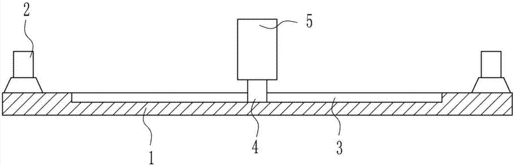
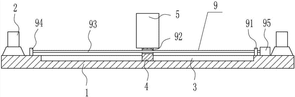
[0029] A kind of oil pipeline cutting equipment, such as Figure 1-5 As shown, it includes a base 1, a support base 2, a first slider 4, a hollow cylinder 5, a cutting device 7 and a walking device 8. The support base 2 is symmetrically installed on the left and right sides of the top of the base 1, and the top of the base 1 is opened in the middle. There is a chute 3, and the first slider 4 is arranged in the chute 3, and the first slider 4 is slidably matched with the inside of the chute 3. A hollow cylinder 5 is installed on the top of the first slider 4, and the center of the left side of the hollow cylinder 5 is located There is a placement hole 6 at the center of the circle on the right side, and a running device 8 is provided on the left side of the hollow tube 5 , and a cutting device 7 is provided on the moving parts of the running device 8 .

Embodiment 2

[0031] A kind of oil pipeline cutting equipment, such as Figure 1-5 As shown, it includes a base 1, a support base 2, a first slider 4, a hollow cylinder 5, a cutting device 7 and a walking device 8. The support base 2 is symmetrically installed on the left and right sides of the top of the base 1, and the top of the base 1 is opened in the middle. There is a chute 3, and the first slider 4 is arranged in the chute 3, and the first slider 4 is slidably matched with the inside of the chute 3. A hollow cylinder 5 is installed on the top of the first slider 4, and the center of the left side of the hollow cylinder 5 is located There is a placement hole 6 at the center of the circle on the right side, and a running device 8 is provided on the left side of the hollow tube 5 , and a cutting device 7 is provided on the moving parts of the running device 8 .

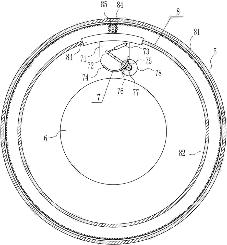
[0032] Cutting device 7 comprises mounting plate 71, fork 72, electric push rod 73, arc slide rail 74, arc slide block 75, conn...

Embodiment 3

[0034] A kind of oil pipeline cutting equipment, such as Figure 1-5 As shown, it includes a base 1, a support base 2, a first slider 4, a hollow cylinder 5, a cutting device 7 and a walking device 8. The support base 2 is symmetrically installed on the left and right sides of the top of the base 1, and the top of the base 1 is opened in the middle. There is a chute 3, and the first slider 4 is arranged in the chute 3, and the first slider 4 is slidably matched with the inside of the chute 3. A hollow cylinder 5 is installed on the top of the first slider 4, and the center of the left side of the hollow cylinder 5 is located There is a placement hole 6 at the center of the circle on the right side, and a running device 8 is provided on the left side of the hollow tube 5 , and a cutting device 7 is provided on the moving parts of the running device 8 .

[0035] Cutting device 7 comprises mounting plate 71, fork 72, electric push rod 73, arc slide rail 74, arc slide block 75, co...


PUM


Abstract

The invention relates to cutting equipment, in particular to cutting equipment for a petroleum pipeline. According to the cutting equipment for the petroleum pipeline, the time and labor are saved, manual cutting is not needed, and cutting injuries are avoided in the cutting process. The cutting equipment for the petroleum pipeline comprises a base and the like; supporting seats are symmetricallymounted on the left and right sides of the top of the base; a sliding groove is formed in the middle of the top of the base and internally provided with a first sliding block, and the first sliding block and the interior of the sliding groove are in slide fit; a hollow cylinder is mounted on the top of the first sliding block; storing holes are formed in the circle center of the left side face andthe circle center of the right side face of the hollow cylinder correspondingly; and a travelling device is arranged on the left side face in the hollow cylinder. A saw disc can be driven by the travelling device to rotate around the petroleum pipeline for comprehensive cutting, and the effects that the time and the labor are saved, manual cutting is not needed, and the cutting injuries are avoided in the cutting process are achieved.

Description

technical field [0001] The invention relates to a cutting device, in particular to an oil pipeline cutting device. Background technique [0002] Oil pipelines are composed of oil pipes and their accessories, and are equipped with corresponding oil pump units according to the needs of the process, designed and installed as a complete pipeline system to complete the tasks of oil loading, unloading and transportation. [0003] In the laying of oil pipelines, in order to make the oil pipelines reach the required length, the oil pipelines will be cut, which is convenient to use. However, when the oil pipelines are cut manually, it is time-consuming and laborious, and the oil pipelines are too large to be convenient for people to cut. Therefore, it is urgent to develop an oil pipeline cutting equipment that saves time and effort, does not require people to cut, and will not be cut during the cutting process. Contents of the invention [0004] (1) Technical problems to be solved...

Claims


Application Information

Patent Timeline
Patent Type & Authority Applications(China)
IPC IPC(8): B23D45/12
CPCB23D45/126
Inventor 范郑卓梁永养毛忠滢
Owner 新昌县益旭龙机械科技有限公司
Why Eureka
Try Eureka