Manufacturing method of flyback transformer

A manufacturing method and high-voltage package technology, applied in coil manufacturing, inductance/transformer/magnet manufacturing, transformers, etc., can solve the problems of winding copper wire breakdown, waste material of wrapping tape, difficult penetration of epoxy resin, etc., to improve the durability The effect of high pressure aging ability, high production efficiency and low labor unit price

Inactive Publication Date: 2014-12-10
佛山市顺德区铭派电子有限公司
View PDF3 Cites 3 Cited by
  • Summary
  • Abstract
  • Description
  • Claims
  • Application Information

AI Technical Summary

Problems solved by technology

[0005] 1. When the high-voltage package is filled with primary glue, since the tape is wound on the primary magnetic core, it is difficult for the epoxy resin to penetrate into the tape, which leads to the breakdown of the winding copper wire during the use of the product;
[0006] 2. When the primary magnetic core of the high-voltage package is wrapped with tape, the tape is easy to adhere to impurities, which may easily cause flash fire inside the product and cause the product to be scrapped;
[0007] 3. The primary wrapping tape of the high-pressure package, the product is exposed to high temperature of 80°C to 120°C and low temperature of -5°C to -20°C, the tape will ag

Method used


Image

  • Manufacturing method of flyback transformer
  • Manufacturing method of flyback transformer

Examples


Embodiment Construction

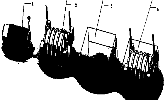
[0043] A method for manufacturing a high pressure bag, comprising the steps of:

[0044] (1) Set the number of coils to be wound;

[0045] (2) Fix the primary magnetic rod to be wound on the jig;

[0046] (3) The length of the thread is reserved enough for the product;

[0047] (4) The end of the thread is close to the edge of the jig and wound in a counterclockwise direction, and the end of the thread is pressed against the end of the thread that has been wound around at the 1 / 2 of the opposite side of the magnetic rod; parallel to the first round of copper that has been wound According to different wire diameters, use 0.5-2 kg to fix the end of the wire;

[0048] (5) The wire end is drawn vertically along the surface of the magnetic rod to the end of the magnetic rod, and the wire end is fixed with a force of 0.5-2 kg according to different wire diameters, and the winding of the equipment is started;

[0049] (6) The tail of the wire is close to the end of the winding of ...


PUM


Abstract

The invention discloses a manufacturing method of a flyback transformer. The manufacturing method comprises steps as follows: (1), the winding number of coils is set; (2), a to-be-wound primary magnetic bar is fixed on a jig; (3), a wire head with required length by a product is reserved; (4), the wire head winds tightly along the edge of the jig for one circle counterclockwise, and a wire tail presses the wire head which winds for one circle in a 1/2 position of a reverse side of the magnetic bar, is parallelly attached to the first circle of copper wire which finishes winding, and is fixed; (5), the wire head is perpendicularly guided out to the tail end of the magnetic bar along the surface of the magnetic bar and is fixed, and equipment is started for winding; (6), the wire tail is tightly attached to the tail end of a winding, a knot is tied in a cross manner, and the wire tail is cut off according to the required length after winding to form a semi-finished product for standby application; (7), during later process production, the knot tied on the primary magnetic bar is untied in the direction opposite to the tying direction, and the wire head or the wire tail is connected to the corresponding position according to requirements of a product; and (8), potting is performed. With the adoption of the manufacturing technology, the voltage withstanding property and the anti-ageing property of the product are improved, the production efficiency is high, and the service life of the product is prolonged remarkably.

Description

technical field [0001] The invention relates to a method for manufacturing a high-voltage bag, in particular to a high-voltage bag applied to a gas pulse igniter, an ozone generator, and an anion generator. Background technique [0002] The high-voltage pack is the energy supply device for the pulse igniter, ozone generator, and negative ion generator. Its first function is to provide high-voltage output for the pulse igniter, and its second function is to provide energy for the ozone generator and negative ion generator. The magnetic core provides energy for the high voltage pack. [0003] In the current production process of the high-voltage package primary magnetic core, after the enameled wire is wound on the magnetic rod, a layer of tape needs to be pasted on the wound enameled wire, and the primary winding is fixed with the tape. During the assembly process of the high-voltage package, the primary magnetic core and the secondary magnetic core need to be combined, and ...

Claims


Application Information

Patent Timeline
IPC IPC(8): H01F38/12H01F41/00H01F41/06H01F41/10
Inventor 陈阳
Owner 佛山市顺德区铭派电子有限公司
Why Eureka
Try Eureka