A multifunctional ice-breaking snowplow

A snow plow, multi-functional technology, applied in snow surface cleaning, construction, cleaning methods, etc., can solve the problem of inability to carry out secondary cleaning, and achieve the effect of improving ice breaking efficiency, improving snow sweeping efficiency, and protecting integrity.

Inactive Publication Date: 2019-06-21
EAST CHINA JIAOTONG UNIVERSITY
View PDF8 Cites 0 Cited by
  • Summary
  • Abstract
  • Description
  • Claims
  • Application Information

AI Technical Summary

Problems solved by technology

[0004] In order to overcome the hard snow shoveling device and its application described in the background art, during the ice-breaking and snow-shoveling process, there are ice-breaking fragments between the snow-shoveling blades, the residual snow may condense into ice again, and the snow-sweeping device at the rear of the vehicle clears the residual ice and residual snow. In the process, some small ice and snow cannot be cleaned up again when the ice cannot be broken. The present invention provides a multi-functional ice-breaking and snow-plowing vehicle. Power, the ice breaking device at the front of the front of the car uses the expansion and contraction of the hydraulic cylinder to bring the ice breaking device close to the ground. During the forward process of the vehicle, the spiral drum rotates to break the ice. In order to avoid the gap between the spiral ice breaking grooves during the ice breaking process of the spiral drum The remaining ice and snow condense into ice for the second time. A strip-shaped heat dissipation resistor is specially designed at the gap inside the spiral drum. The strip-shaped heat dissipation resistor can melt the broken ice and snow in the gap by heating. At the same time, a salt sprinkler is added behind the snow removal device at the tail , making use of the characteristics that the salt-snow mixture is easy to freeze, under some low temperature conditions, it is beneficial to improve the secondary cleaning of the tail snow removal device

Method used


Image

  • A multifunctional ice-breaking snowplow
  • A multifunctional ice-breaking snowplow
  • A multifunctional ice-breaking snowplow

Examples


Embodiment Construction

[0021] The present invention will be further described below in conjunction with the drawings and embodiments:

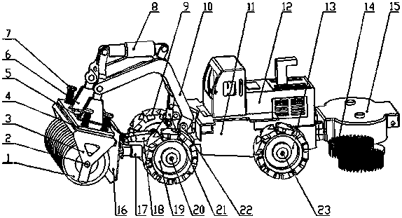
[0022] As attached figure 1 As shown, the present invention includes a spiral roller 1, a roller shaft 2, a cage 3, a support plate 4, a shock-absorbing spring 5, a front beam 6, a set screw 7, a hydraulic lever I8, a wheel I9, a bending frame support beam 10, a car Body chassis 11, cab 12, wheel IV13, snow removal device 14, tail device 15, snow shovel I16, hydraulic lever VI17, hydraulic lever IV18, wheel II19, axle I20, hydraulic lever II21, front support frame 22, axle II23 .

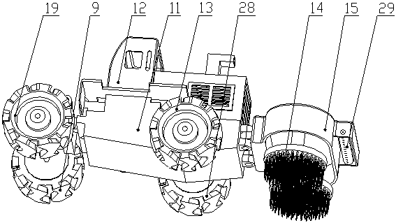
[0023] As attached figure 2 As shown, the present invention includes wheel I9, vehicle body chassis 11, cab 12, wheel IV13, snow removal device 14, tail device 15, wheel II19, wheel III28, and salt spray device 29.

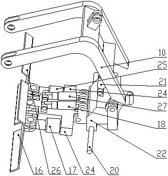
[0024] As attached image 3 As shown, the present invention includes curved support beam 10, snow shovel I16, hydraulic rod VI17, hydraulic rod IV18, shaft I20, hydraulic rod II21...


PUM


Abstract

The invention discloses a multi-functional ice-breaking and snow-plowing vehicle, which comprises a spiral drum, a cage, a support plate, a shock-absorbing spring, a front beam, a curved frame support beam, a car body chassis, a cab, a snow-plowing device, a tail device, and a snow-plowing vehicle. Plate, hydraulic rod, front support frame, salt spreading device, strip resistance and so on. The road ice-breaking and snow-shoveling device places the ice-breaking and snow-shoveling device at the front of the vehicle. After the road surface is broken by the spiral drum, the snow-shoveling board is used to push the ice-breaking and snow to both sides of the road. Realize secondary snow removal, thereby improving the efficiency of the entire ice-breaking and snow-plowing vehicle for road ice and snow treatment. The emitted heat can melt the corresponding ice and snow. The road ice-breaking and snowplow device has a compact design and is easy to operate, and is especially suitable for areas with a lot of snow and some roads that are prone to secondary icing.

Description

Technical field [0001] The invention relates to a road ice-breaking and snow-shoveling vehicle, in particular to a multifunctional ice-breaking and snow-shoveling vehicle. Background technique [0002] The ice-breaking and snow-shoveling truck is a kind of snow-removing vehicle that uses mechanical parts to close the ice on the road surface to clean the ice. Generally, the ice-breaking and snow-removing device is usually placed at the front of the vehicle, and the ice is pressed by a hydraulic lever. Compaction and processing of blocks. [0003] Commonly used ice-breaking and snow-removing devices include manual push shovel, large snowplow, ice-breaking shovel, etc. Most snow removal devices use manual ice breaking and cleaning. In the actual process, some thicker ice blocks can not only be broken, but also cause some trouble to the construction personnel. The occurrence of slipping phenomenon increases the ice breaking and snow removal to a certain extent. Difficulty, but also r...

Claims


Application Information

Patent Timeline
Patent Type & Authority Patents(China)
IPC IPC(8): E01H5/12
CPCE01H5/12
Inventor 王朝兵彭玲阳刘乐平贾文强张龙唐晓红
Owner EAST CHINA JIAOTONG UNIVERSITY
Why Eureka
Try Eureka