Ceiling machine

A ceiling machine and annular technology, which is applied in the field of air conditioners, can solve the problems of small air outlet angle of ceiling machines.

Pending Publication Date: 2018-04-06
GD MIDEA AIR-CONDITIONING EQUIP CO LTD +1
View PDF0 Cites 0 Cited by
  • Summary
  • Abstract
  • Description
  • Claims
  • Application Information

AI Technical Summary

Problems solved by technology

[0003] The main purpose of the present invention is to propose a smallpox machine, which aims

Method used

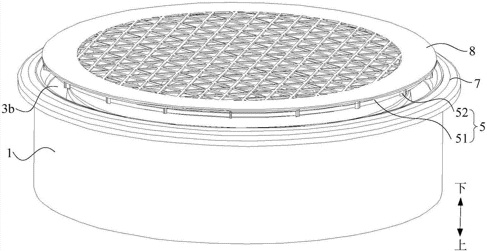
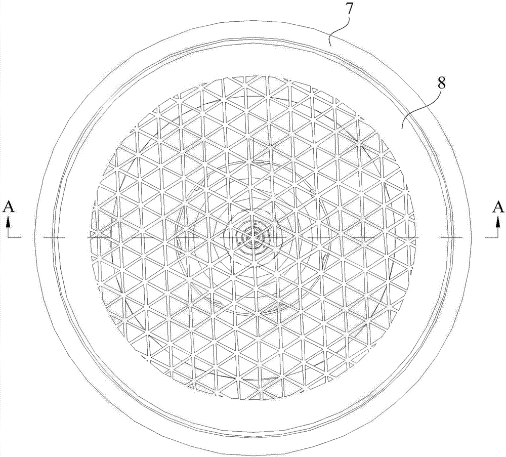
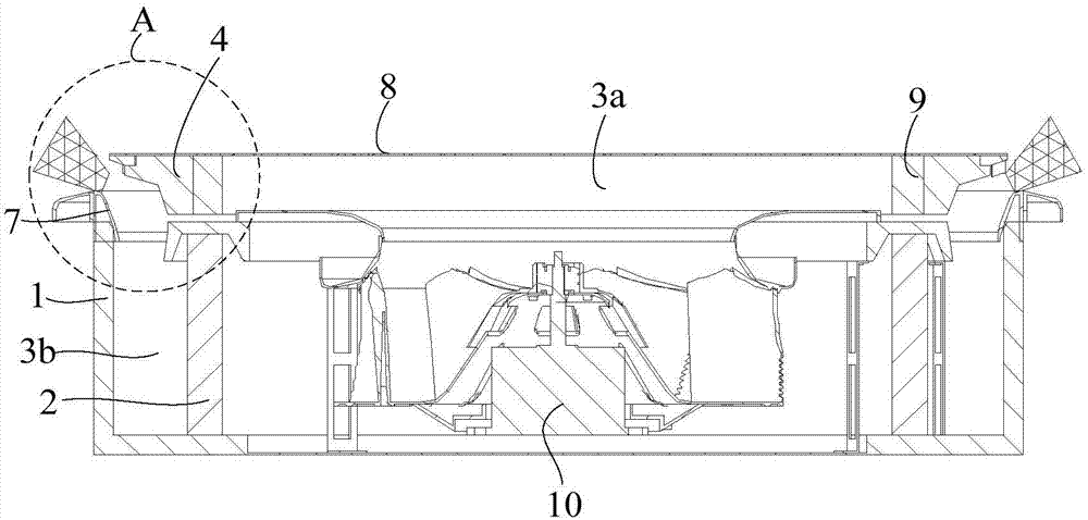

Image

  • Ceiling machine
  • Ceiling machine
  • Ceiling machine

Examples


Embodiment Construction

[0027] The following will clearly and completely describe the technical solutions in the embodiments of the present invention with reference to the accompanying drawings in the embodiments of the present invention. Obviously, the described embodiments are only part of the embodiments of the present invention, not all of them. Based on the embodiments of the present invention, all other embodiments obtained by persons of ordinary skill in the art without creative efforts fall within the protection scope of the present invention.

[0028] It should be noted that if there is a directional indication (such as up, down, left, right, front, back...) in the embodiment of the present invention, the directional indication is only used to explain the position in a certain posture (as shown in the accompanying drawing). If the specific posture changes, the directional indication will also change accordingly.

[0029] In addition, if there are descriptions involving "first", "second" and ...


PUM


Abstract

The invention discloses a ceiling machine comprising a shell and a heat exchanger arranged inside the shell. The heat exchanger and the shell are enclosed to form an annular outlet air duct. The ceiling machine also includes an annular air-guiding member and a rotating wheel assembly. The annular air-guiding member is installed at an air outlet of the outlet air duct. The rotating wheel assembly includes a rotating wheel and a driving device. The rotating wheel includes a ring-shaped body and fan blades disposed on the ring-shaped body, and the annular air-guiding member is sleeved with the ring-shaped body. One ends of fan blades are connected with the ring-shaped body, and the other ends of fan blades extend to the air outlet. The driving device is connected with the rotating wheel to drive the rotating wheel to rotate. The range of the outlet angle of the ceiling machine is relatively large.

Description

technical field [0001] The invention relates to the technical field of air conditioning, in particular to a ceiling machine. Background technique [0002] The ceiling machine can be widely used in hospitals, hotels, office buildings and other places. At present, most of the ceiling machines are generally of rectangular structure, and the air outlets of the ceiling machines are usually arranged around the ceiling machines. Specifically, a narrow and long opening is respectively arranged around the ceiling machine as an air outlet, and there is no connection between the four air outlets. Each air outlet basically adopts an air deflector to guide the air, and the air outlet angle of the ceiling machine is controlled by driving the air deflector to swing. However, with this air guiding method, the air outlet angle of the ceiling machine is smaller and the air volume is less. Contents of the invention [0003] The main purpose of the present invention is to propose a smallpo...

Claims


Application Information

Patent Timeline
IPC IPC(8): F24F1/00F24F13/14F24F13/22
CPCF24F1/0007F24F1/0047F24F13/1413F24F13/1426F24F13/222
Inventor 唐清生
Owner GD MIDEA AIR-CONDITIONING EQUIP CO LTD
Why Eureka
Try Eureka