Generator assembly tooling and assembly method

A technology for assembling tooling and generators, which is applied in the manufacture of motor generators, electromechanical devices, electrical components, etc. It can solve problems such as complex repair work, deformation of the rotor yoke, and reduced service life of the generator, so as to save assembly hours and avoid Radial deformation, the effect of saving assembly cost

Active Publication Date: 2019-08-09
BEIJING GOLDWIND SCI & CREATION WINDPOWER EQUIP CO LTD
View PDF5 Cites 0 Cited by
  • Summary
  • Abstract
  • Description
  • Claims
  • Application Information

AI Technical Summary

Problems solved by technology

[0004] This method can assist the assembly of the stator and the rotor. At the same time, there are still some problems in this method. First, the yoke of the rotor is similar to a cantilever beam during the assembly process, and the yoke is always subjected to the force generated by the magnetic pole and the stator core. As the coincidence with the iron core increases, the force on the yoke gradually increases, so it may cause deformation of the rotor yoke
The second is that after the sliding sleeve is separated from the rotor, the rotating shaft needs to be installed. At this time, the rotor lacks fixed constraints, so the rotor and stator are also prone to adsorption
Moreover, after the magnetic poles and iron cores are damaged, because the follow-up repair work is more complicated and the reliability after repair is poor, it will bring economic losses while reducing the quality of the generator and reducing the service life of the generator

Method used


Image

  • Generator assembly tooling and assembly method
  • Generator assembly tooling and assembly method
  • Generator assembly tooling and assembly method

Examples


Embodiment Construction

[0062] Features and exemplary embodiments of various aspects of the invention will be described in detail below. In the following detailed description, numerous specific details are set forth in order to provide a thorough understanding of the present invention. It will be apparent, however, to one skilled in the art that the present invention may be practiced without some of these specific details. The orientation words appearing in the following description are the directions shown in the figure, and do not limit the specific structure of the generator assembly tool of the present invention.

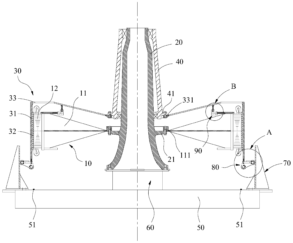
[0063] The assembly tooling of the generator provided by the embodiment of the present invention can assist the rotor and stator of the generator to be assembled, especially for the permanent magnet generator in the technical field of wind power generation. In order to ensure the power generation, the diameter of the permanent magnet generator is relatively large , and the uniformity ...


PUM


Abstract

Provided are an assembly tool and an assembly method for a generator. One of a rotor and a stator of the generator serves as a sleeved member, and the other one serves as a sleeving member. The assembly tool comprises: a limiting device arranged around a pre-determined axis and defining an assembly space on a side that faces the pre-determined axis, the limiting device having a guide face facing the assembly space and extending along the pre-determined axis; and a servo guide device comprising a connecting portion and a first abutting portion connected to the connecting portion, wherein when the servo guide device is connected to the sleeving member by means of the connecting portion, the first abutting portion can extend to the outside of the sleeving member in a radial direction of the sleeving member, wherein the first abutting portion can abut against the guide face and move along the guide face, such that an air gap between the sleeving member and the sleeved member is kept constant. Therefore, during assisting in the sleeving of the sleeving member on the sleeved member, the assembly tool of the embodiments of the disclosure can ensure the uniformity of the air gap between the sleeving member and the sleeved member, thereby preventing the sleeving member from deformation which even results in damage to a rotor magnetic pole and a stator core.

Description

technical field [0001] The invention relates to the technical field of generators, in particular to a generator assembly tool and an assembly method. Background technique [0002] A low-speed and large-diameter generator consists of a stator and a rotor, such as a permanent magnet generator in a wind turbine. For example, an outer rotor type generator, the rotor is coaxially sleeved outside the stator, and the rotor can surround the central axis of the stator rotate. The permanent magnets inside the rotor are evenly arranged along the circumference. Since these permanent magnets are usually made of NdFeB permanent magnet materials with good magnetic properties, and NdFeB magnets have strong magnetism, the rotor and stator are assembled During the process, when the rotor is close to the stator, under the action of the large adsorption force generated by the permanent magnet, the rotor and the stator core are easily attracted to each other and collide. If the necessary measu...

Claims


Application Information

Patent Timeline
Patent Type & Authority Patents(China)
IPC IPC(8): H02K15/03
CPCH02K15/03
Inventor 李延慧杨景超王旭
Owner BEIJING GOLDWIND SCI & CREATION WINDPOWER EQUIP CO LTD
Why Eureka
Try Eureka