Roof antenna

A roof antenna and antenna technology, applied in antennas, folded antennas, antenna arrays, etc., can solve problems such as impact, vulnerability to lightning damage, etc.

Inactive Publication Date: 2018-04-10
辜红珍
View PDF0 Cites 0 Cited by
  • Summary
  • Abstract
  • Description
  • Claims
  • Application Information

AI Technical Summary

Problems solved by technology

However, when the antennas currently on the market are installed on the

Method used


Image

  • Roof antenna

Examples


Embodiment

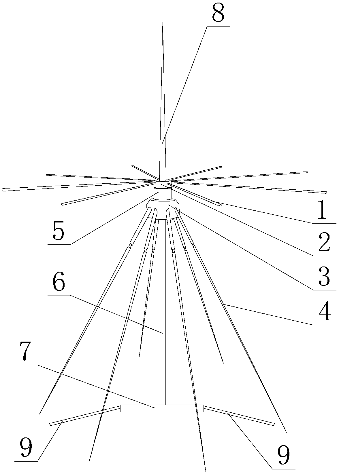
[0016] like figure 1 As shown, a roof antenna includes a first filter 2 and a second filter 3, the first filter 2 is located above the second filter 3 and connected to each other through a rotating shaft 5, and also includes a pole 6 and a chassis 7, so One end of the support rod 6 is fixed on the bottom of the second filter 3, and the other end of the support rod 6 is connected to the top surface of the chassis 7. The chassis 7 is provided with a plurality of screw holes, and the top of the first filter 2 is provided with There is a detachable lightning rod 8, the chassis 7 is provided with a plurality of fixed claws 9, and also includes a plurality of top antennas 1 and a plurality of bottom antennas 4, the top antenna 1 is connected to the first filter 2, the The bottom antenna 4 is connected to the second filter 3, and the bottom antenna 4 is divided into two sections, and the two sections are hinged to each other.


PUM


Abstract

The invention discloses a roof antenna, which mainly relates to communication equipment. The invention includes a first filter and a second filter. The first filter is located above the second filter and connected to each other through a rotating shaft. It also includes a pole and a Chassis, one end of the pole is fixed on the bottom of the second filter, the other end of the pole is connected to the top surface of the chassis, the chassis is provided with a plurality of screw holes, and the top of the first filter is provided with a detachable The lightning rod is provided with a plurality of fixing claws on the chassis; the lightning rod is used to prevent the invention from being damaged by lightning, and the fixing claws can make the invention firmly fixed on the carrier.

Description

technical field [0001] The invention relates to communication equipment, in particular to a roof antenna. Background technique [0002] With the rapid development of today's society, radio has played an increasingly important role in people's lives. Radio communication signals have penetrated into every aspect of people's lives, and people have higher and higher requirements for signal transmission quality and distance. , the signal transmission quality of antennas currently on the market is good. Due to the excellent signal quality and light overall structure of the antenna, it is often used for communication. However, the current antennas on the market are easily damaged and affected by lightning when they are installed on the roof for wireless TV. Contents of the invention [0003] In view of the above problems, the present invention provides a roof antenna, which can effectively prevent lightning from damaging the antenna itself when in use. [0004] The purpose of t...

Claims


Application Information

Patent Timeline
IPC IPC(8): H01Q1/50H01Q1/08H01Q1/12H01Q21/00
CPCH01Q1/50H01Q1/08H01Q1/084H01Q1/12H01Q1/1242H01Q21/00
Inventor 辜红珍
Owner 辜红珍
Why Eureka
Try Eureka