
Directional riveting mechanism for motor end cover and electric power pipe fitting

A technology of motor end cover and riveting mechanism, applied in the direction of electrical components, electric components, manufacturing motor generators, etc., can solve the problems of increasing process complexity, reducing riveting efficiency, increasing riveting time consumption, etc.

Inactive Publication Date: 2018-04-13
CHONGQING RYAN PAINT CO LTD
View PDF6 Cites 10 Cited by
  • Summary
  • Abstract
  • Description
  • Claims
  • Application Information

AI Technical Summary

Problems solved by technology

Although this device can complete the riveting of the combination of pipe fittings and other objects, it needs to carry out end treatment on the pipe fittings first, which increases the complexity of the process. Although the riveting quality is improved to a certain extent, it increases the time consumption of riveting and reduces the riveting efficiency

Method used


Image

  • Directional riveting mechanism for motor end cover and electric power pipe fitting
  • Directional riveting mechanism for motor end cover and electric power pipe fitting
  • Directional riveting mechanism for motor end cover and electric power pipe fitting

Examples


Embodiment Construction

[0044]The following will clearly and completely describe the technical solutions in the embodiments of the present invention with reference to the accompanying drawings in the embodiments of the present invention. Obviously, the described embodiments are only some, not all, embodiments of the present invention. Based on the embodiments of the present invention, all other embodiments obtained by persons of ordinary skill in the art without making creative efforts belong to the protection scope of the present invention.

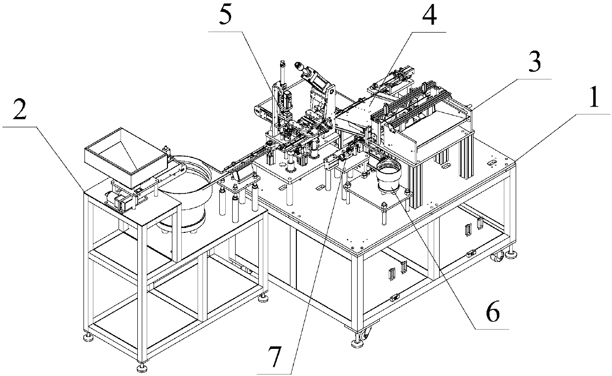
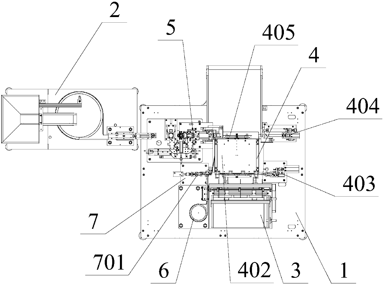
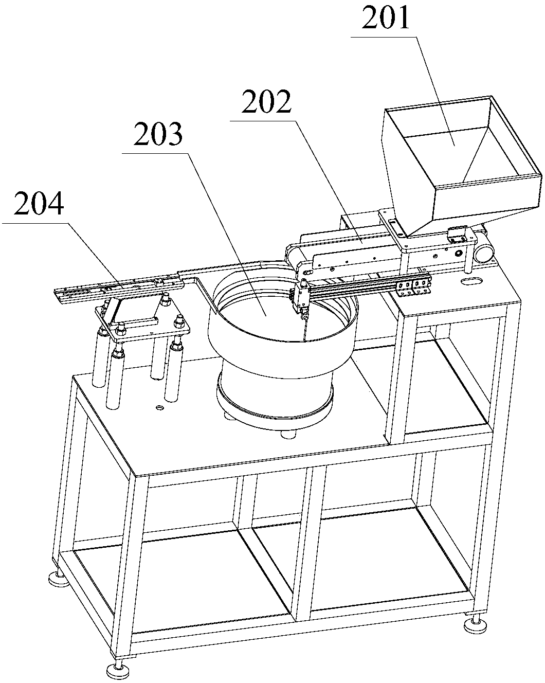
[0045] Such as Figure 1-22 As shown, a riveting equipment for motor end cover and power pipe fittings, such as Figure 1~2 As shown: it includes a chassis 1 and an end cap feeding mechanism 2, and the chassis 1 is provided with a sorting and transferring mechanism for electric pipe fittings applied to riveting equipment and a directional riveting mechanism 5 for riveting the pipe fittings transferred by the moving mechanism 4 (that is, the directional riveting...


PUM


Abstract

The invention provides a directional riveting mechanism for a motor end cover and an electric power pipe fitting. The directional riveting mechanism for the motor end cover and the electric power pipefitting includes an end cover material-collecting device, a displacement unit, a location unit and a riveting unit, the end cover material-collecting device is connected with an end cover direct-shaking feeder and also arranged at the tail end of the end cover direct-shaking feeder, and the end cover material-collecting device is used to collect an end cover which is transported by the end coverdirect-shaking feeder; the end cover material-collecting device includes a material-collecting support, a material-collecting notch, a step-shaped mandril and a jacking driving air cylinder, wherein,the material-collecting notch is formed in the top end of the material-collecting support, and the material-collecting notch rightly faces the end cover direct-shaking feeder and is flush with a guiding rail, for transporting the end cover, on the end cover direct-shaking feeder; and the jacking driving air cylinder is used to drive the step-shaped mandril to jack the end cover which is located inthe material-collecting notch. According to the directional riveting mechanism for the motor end cover and the electric power pipe fitting, the motor end cover can be accurately collected, located and transferred, and the motor end cover and the electric power pipe fitting are in butt joint accurately are riveted.

Description

technical field [0001] The invention relates to the technical field of automatic assembly of electric equipment, and more specifically, relates to a directional riveting mechanism for motor end covers and electric pipe fittings. Background technique [0002] In the previous riveting of workpieces, it was generally operated manually, but manual operation is prone to errors, which directly affects the service life of the product, and the work efficiency of the workers is low, which increases the production cost. However, the existing riveting machine has a complex structure. The operation is inconvenient and the cost is high. In view of this, it is necessary to improve the existing riveting machine. [0003] Moreover, in life and production (including power equipment production), many products are connected by multiple pipe fittings. At present, there are roughly three connection methods for pipe fittings. One is to use welding, but the surface of metal pipe fittings will be d...

Claims


Application Information

Patent Timeline
Patent Type & Authority Applications(China)
IPC IPC(8): B21D39/00B21D43/02B21D43/14B21D43/00B21D45/02H02K15/14
CPCB21D39/00B21D43/003B21D43/02B21D43/14B21D45/02H02K15/14
Inventor 张健
Owner CHONGQING RYAN PAINT CO LTD
Learn More