
A slider-type die frictionless riveting connection method for lightweight plates

A slide type, riveting connection technology, applied in the direction of forming tools, metal processing equipment, manufacturing tools, etc., can solve the problems of low processing difficulty of slide type die, reduce riveting force, strong applicability, etc., to reduce riveting Defects, reducing riveting force, and the effect of strong applicability

Active Publication Date: 2019-12-27
XI AN JIAOTONG UNIV
View PDF5 Cites 2 Cited by
  • Summary
  • Abstract
  • Description
  • Claims
  • Application Information

AI Technical Summary

Problems solved by technology

[0003] In order to overcome the above-mentioned shortcomings of the prior art, the object of the present invention is to provide a frictionless rivetless connection method of the slider type concave die for lightweight plates, so as to realize the rivetless connection between the same or different low-plastic lightweight plates at room temperature , the slider-type die used has low processing difficulty, strong applicability and long service life, can obtain riveted joints without cracks, reduce the required riveting force, reduce riveting defects, improve the strength of riveted joints, and have higher efficiency, Advantages of easy operation and lower energy consumption

Method used


Image

  • A slider-type die frictionless riveting connection method for lightweight plates
  • A slider-type die frictionless riveting connection method for lightweight plates
  • A slider-type die frictionless riveting connection method for lightweight plates

Examples


Embodiment Construction

[0023] The present invention will be described in detail below in conjunction with the accompanying drawings.

[0024] A sliding block type concave die frictionless riveting connection method for lightweight plates, comprising the following steps:

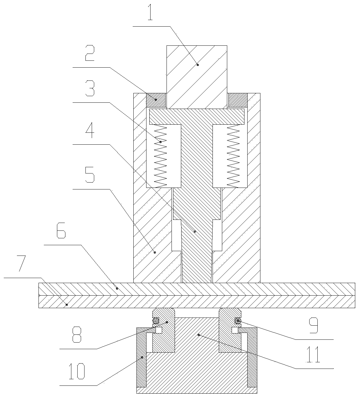
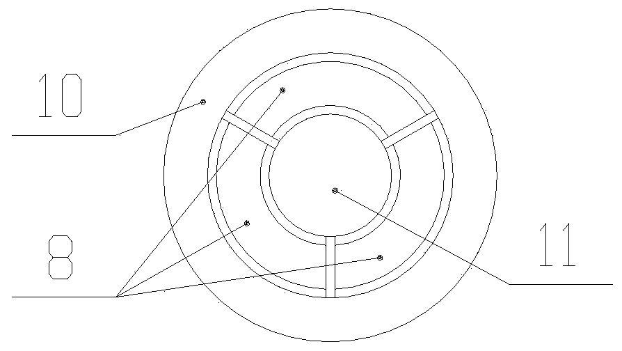
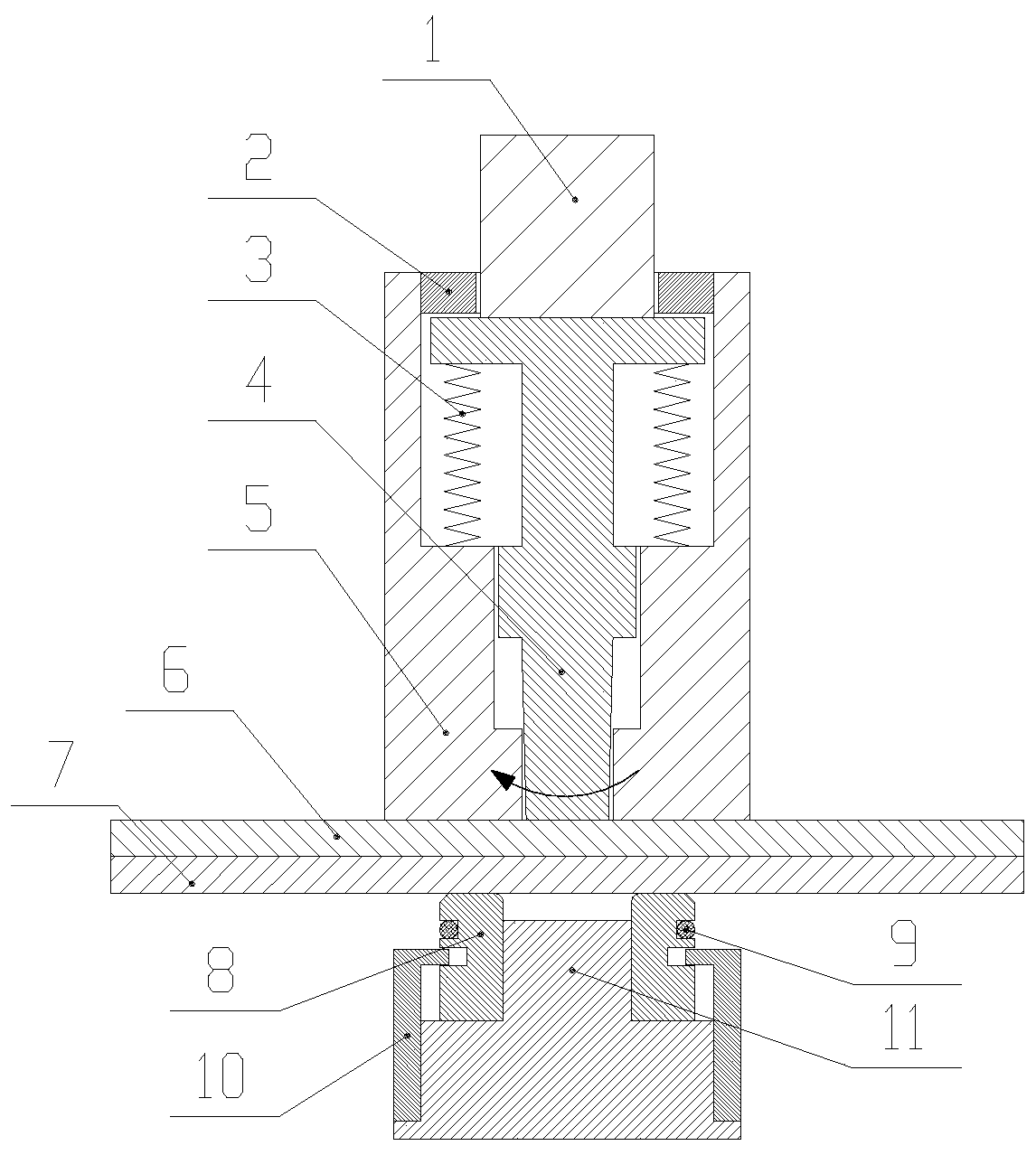
[0025] 1) Positioning stage: refer to figure 1 with figure 2 , before the connection starts, the upper plate 6 and the lower plate 7 are clamped and fixed and stacked on the lower mold, and the lower mold is fixed; the friction head 5 and the upper punch 4 move downward as a whole, and the friction head 5 and the upper punch 4 The upper plate 6 and the lower plate 7 are partially positioned on the lower mold, and pressure is applied; the up and down movement of the upper punch 4 is realized through the joint action of the stamping power source, the pressure head 1 and the ring spring 3, and the upper punch 4 and the ring spring 3 is installed inside the friction head 5 through the retaining ring 2, and the keyway inside the fric...


PUM


Abstract

The invention discloses a sliding block type concave mould friction non-riveting connection method of a lightweight plate. The sliding block type concave mould friction non-riveting connection methodcomprises the steps that a to-be-riveted part is subjected to partial frictional heating through the rotation of a friction head and an upper punch; then the friction head stops rotating and applies blank holding force to the to-be-riveted part, a pressing head enables the upper punch to move downwards under the action of a punching power source, metal of an upper plate and metal of a lower plateflow into a mould cavity of a lower mould, sectioning sliding blocks of the lower mould are forced to flow and expand in the radial directions, the metal of the upper plate and the metal of the lowerplate continue to flow to gaps between the sectioning sliding blocks and gaps between the lower punch and the sectioning sliding blocks till the mould cavity of the lower mould is filled, and an S-shaped mechanical lock is formed between the upper plate and the lower plate; and after the preset base thickness value or pressure is reached, the pressing head and the upper punch move upwards to initial positions, and thus the connection process is finished. A flawless riveting joint can be obtained, required riveting acting force is lowered, the riveting defects are reduced, the strength of the riveting joint is improved, and the sliding block type concave mould friction non-riveting connection method is high in efficiency, easy and simple to implement and low in energy consumption.

Description

technical field [0001] The invention belongs to the technical field of plate connection, and in particular relates to a sliding block type concave die frictionless riveting connection method for lightweight plates. Background technique [0002] Due to the needs of environmental protection and energy saving, lightweight panels are more and more widely used in the fields of aerospace, transportation and electronic products. The problem of connecting lightweight panels of the same material, dissimilar materials, same thickness and different thickness has received extensive attention. The rivetless connection process uses special convex and concave dies to stamp the connecting plates, and uses the plastic deformation ability of the metal to form a mechanical lock through the embedding between the plates to achieve the purpose of connection. However, the traditional integral die without riveting connection is difficult to process, not universally applicable, easy to accumulate d...

Claims


Application Information

Patent Timeline
Patent Type & Authority Patents(China)
IPC IPC(8): B21D39/02B21D37/16B21D37/10
CPCB21D37/10B21D37/16B21D39/026
Inventor 赵升吨张鹏李靖祥陈超韩晓兰石田徹
Owner XI AN JIAOTONG UNIV
Learn More