Rotor wing device with rotating direction area changable function

A rotor and area technology, applied in rotorcraft, transportation and packaging, aircraft, etc., can solve problems such as backward blade stall, forward blade shock wave resistance, and limited rotor speed

Inactive Publication Date: 2018-04-13
江富余
View PDF5 Cites 0 Cited by
  • Summary
  • Abstract
  • Description
  • Claims
  • Application Information

AI Technical Summary

Problems solved by technology

The disadvantage is that when flying horizontally, the forward blades accelerate and the backward blades decelerate, resulting in shock resistance of ...

Method used


Image

  • Rotor wing device with rotating direction area changable function
  • Rotor wing device with rotating direction area changable function
  • Rotor wing device with rotating direction area changable function

Examples


Embodiment Construction

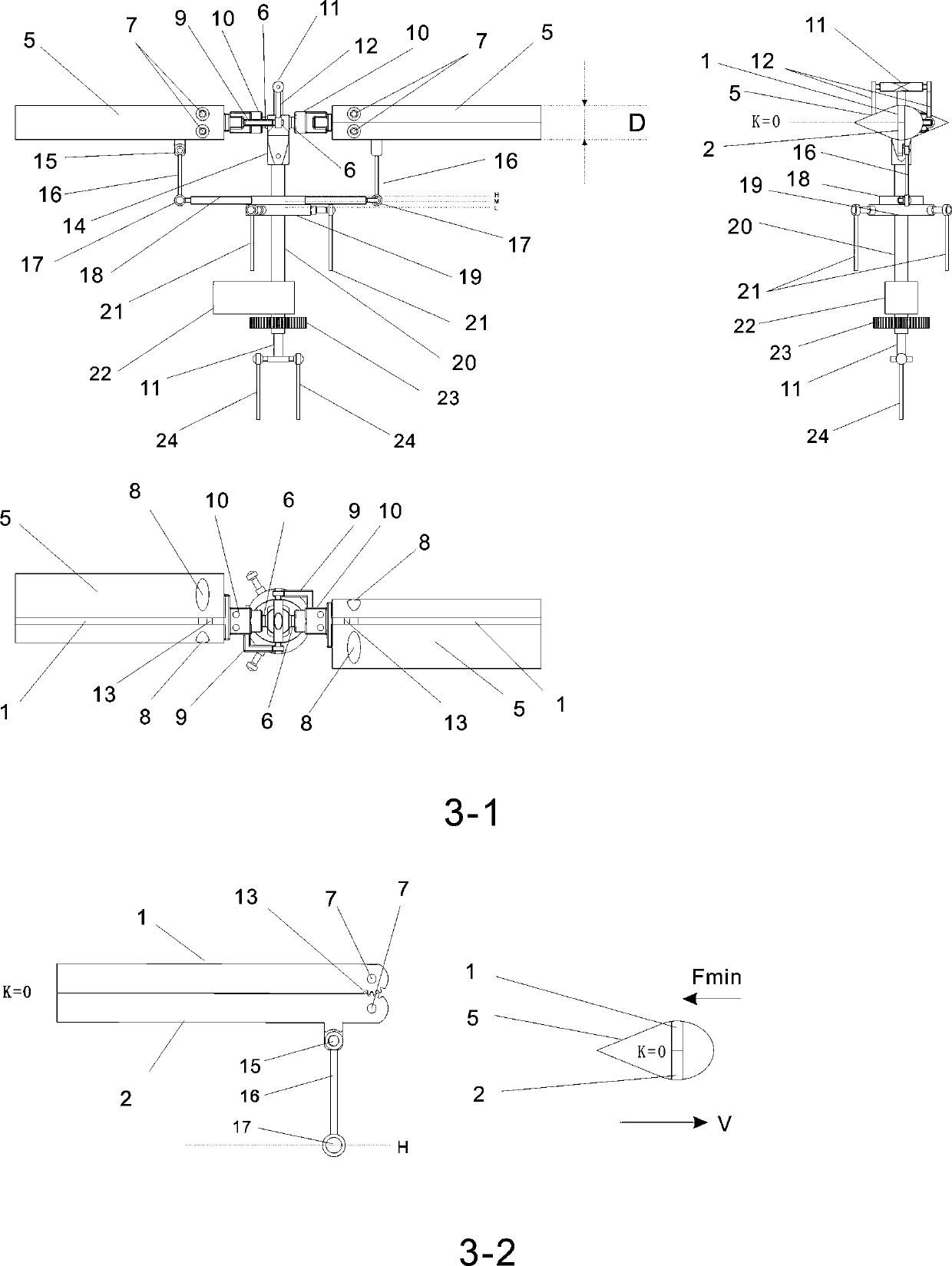
[0181] image 3 It is one of the embodiments of the present invention. The variable rotation area rotor device composed of the maximum thickness slotted blade is called the maximum thickness slotted variable rotation area rotor device. image 3 middle Figure 3-1 Three views of the device.

[0182] image 3 middle Figure 3-1 , The largest thickness slotted blade (5) is connected to the collective pitch shaft (6) of the hub (14) through the blade holder (10), the hub (14) is installed on the rotor main shaft (20), and the other A slotted blade with maximum thickness (5) is installed in the same way on the blade holder (10) on the other side with a phase difference of 180°. The rotor is composed of two slotted blades with maximum thickness (5), The rotor main shaft (20) is hollow. A collective pitch rod (11) is installed in the hollow rotor main shaft (20). The collective pitch rod (11) can be driven by the collective control rod (24) along the hollow rotor main shaft (20) The axi...


PUM


Abstract

A rotor wing device is disclosed. When the rotor wing total distance is zero, opening and closing of upper gap flat plates and lower gap flat plates of rotor wing propeller blades are periodically changed through a rotating oblique disc, or opening and closing of upper front edge blocks and lower front edge blocks of the rotor wing propeller blades are periodically changed through the rotating oblique disc, thus the rotating direction area of the rotor wing propeller blades is periodically changed, and rotor wings generate the periodically-changed resistance difference. The magnitude and direction of the resistance difference are determined by the oblique degree and the oblique direction of the rotating oblique disc. The position where the resistance difference is maximum is always on thepropeller blade on the lowest position when the rotating oblique disc obliques, and the direction of the maximum resistance difference is opposite to the rotating direction of the propeller blade andperpendicular to rotating shafts of the rotor wings. When the rotating oblique disc is not obliquely perpendicular to the rotating shafts at the highest position, the resistance difference is zero, the rotor wing total distance is increased, and tensile force perpendicular to the propeller tip rotating surfaces is generated. The rotor wing device capable of changing the rotating direction area canprovide the tensile force perpendicular to the propeller tip rotating surfaces or the resistance difference perpendicular to the rotating shafts, and the rotor wing device is applied to a fixed-wingaircraft vertically taking off and landing so that vertical taking off and landing and horizontal rapid flight can be achieved.

Description

Technical field [0001] The invention relates to an aerodynamic device, a variable rotation area rotor device, which can provide a pulling force perpendicular to the rotating surface of the propeller tip, and can also provide a pulling force perpendicular to the rotating shaft in the rotating plane of the propeller tip, and is applied to a vertical lifting fixed wing The aircraft can achieve vertical lift and horizontal fast flight without tilting the rotor or the wing of the aircraft. Background technique [0002] At present, the well-known rotor device is a helicopter rotor device, but the helicopter rotor device can only provide a pulling force perpendicular to the rotating surface of the blade tip. It uses a waving device and a periodic pitch changing device to tilt the blade tip rotating surface to drive perpendicular to the blade tip. The pulling force of the rotating surface is also inclined, and the pulling force is divided into the vertical component force and the horizon...

Claims


Application Information

Patent Timeline
IPC IPC(8): B64C27/32B64C27/48B64C27/605
CPCB64C27/32B64C27/48B64C27/605
Inventor 江富余
Owner 江富余
Why Eureka
Try Eureka