An unmanned aerial vehicle with a waist-push power unit

A technology of power plant and unmanned aerial vehicle, applied in the field of unmanned aerial vehicle, can solve the problems of limited flight speed, limited sailing distance, large energy loss, etc., and achieve the effects of increasing horizontal flight speed, precise rotation speed control, and reducing energy consumption

Active Publication Date: 2021-07-30
SUZHOU SAIRONG CONSTITUTION&DECORATION ENG CO LTD
View PDF6 Cites 0 Cited by
  • Summary
  • Abstract
  • Description
  • Claims
  • Application Information

AI Technical Summary

Problems solved by technology

The thrust generated by the propellers of the four-blade vertical UAV is mostly used to offset the gravity of the aircraft, the flight speed is limited and the energy loss is large, and it is only suitable for short-distance applications such as aerial photography and film and television shooting. Although large UAVs with similar shapes to passenger aircraft can achieve The speed is relatively high, but its flight control and attitude adjustment are mostly used in civil aviation airliners. The wings have ailerons for pitch adjustment and tails for heading adjustment. Wings, ailerons, and tails all need structural adjustments, that is, Corresponding driving components need to be installed, the structure of the whole machine is complex, and the overall quality cannot be effectively controlled and reduced, so the energy loss during flight is large, and the voyage distance is also limited
[0004] These problems are particularly prominent in the fields of remote sensing mapping and meteorological data acquisition. Most of the remote sensing mapping and meteorological data acquisition require that the time for cruising and detection in the air can be prolonged or even stay in the air, and the flight speed should be guaranteed. , these requirements are difficult to achieve with existing UAVs

Method used


Image

  • An unmanned aerial vehicle with a waist-push power unit
  • An unmanned aerial vehicle with a waist-push power unit
  • An unmanned aerial vehicle with a waist-push power unit

Examples


Embodiment Construction

[0038] The following will clearly and completely describe the technical solutions in the embodiments of the present invention with reference to the accompanying drawings in the embodiments of the present invention. Obviously, the described embodiments are only some, not all, embodiments of the present invention. Based on the embodiments of the present invention, all other embodiments obtained by persons of ordinary skill in the art without making creative efforts belong to the protection scope of the present invention.

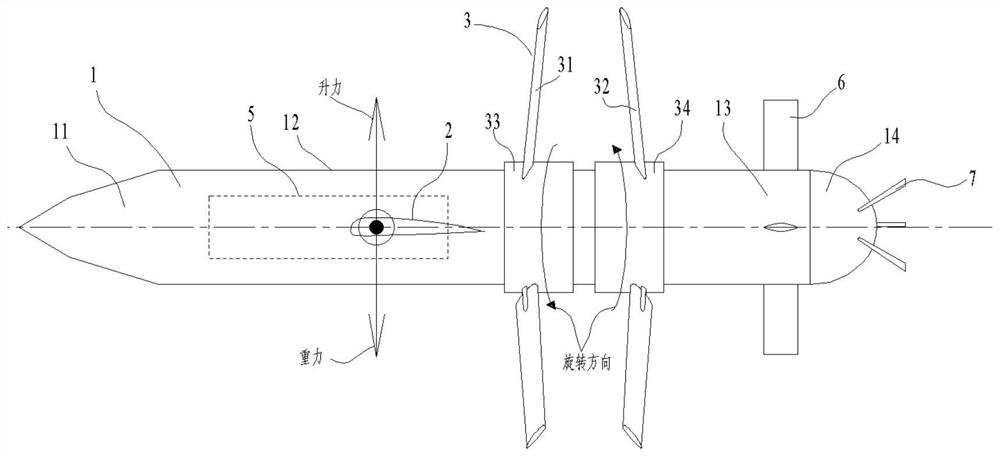
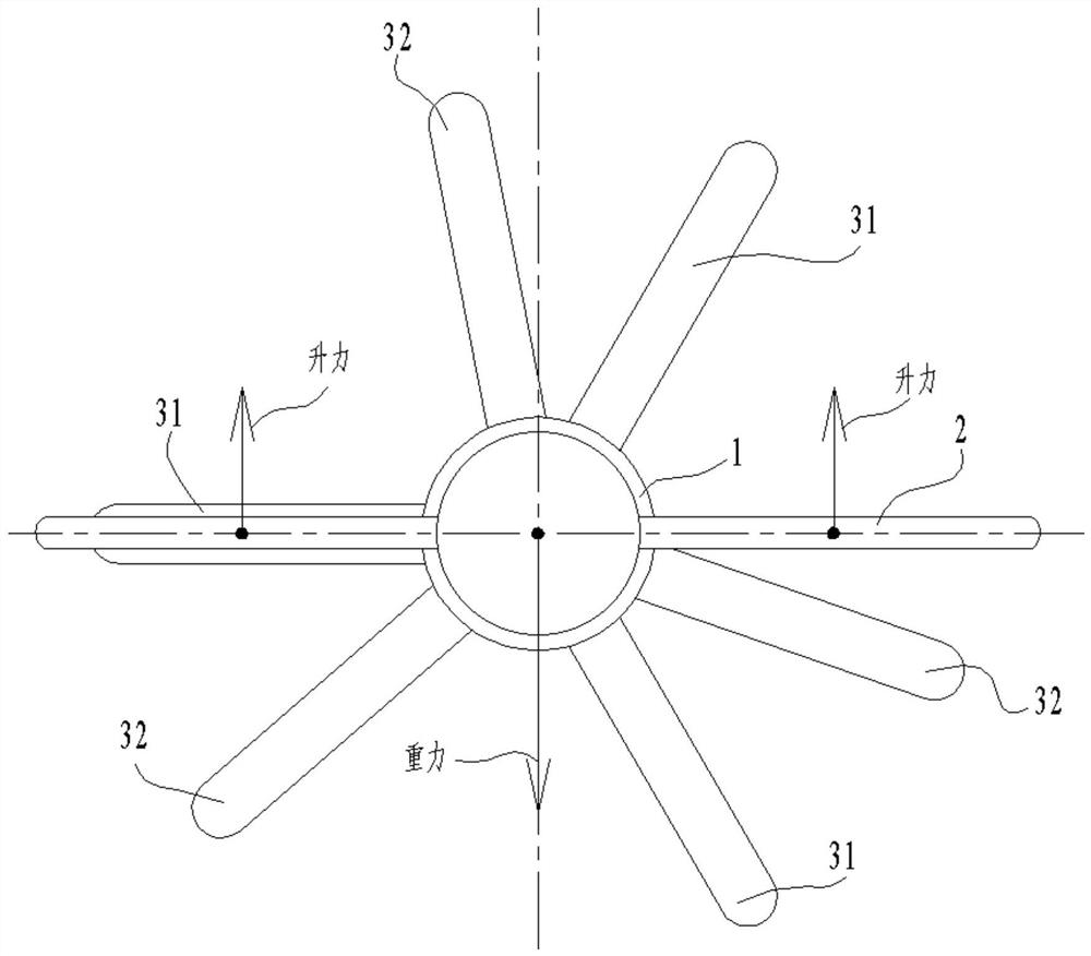
[0039] Such as figure 1 , 2 Shown, a kind of unmanned aerial vehicle with waist-push type power plant, comprises body 1, wing 2 and thruster 3, body 1 is bullet-shaped, body 1 comprises machine head 11, body 12 and machine body that distribute in sequence Belly 13, wing 2 is arranged on fuselage 12, propeller 3 is arranged on belly 13.

[0040] The unmanned aerial vehicle of the present invention is different from the common civilian four-blade vertical take...


PUM


Abstract

The invention discloses an unmanned aerial vehicle with a waist-push power device, which comprises a body, wings and propellers. The fuselage and propellers are arranged on the belly. The propeller includes a first propeller, a second propeller, a first hub and a second hub. The belly is provided with an annular groove-shaped abdominal cavity. The first hub and the second hub are respectively installed on the cylindrical surface at the bottom of the abdominal cavity through bearings. The first The propeller is radially installed on the outer surface of the first hub, and the second propeller is radially installed on the outer surface of the second hub. The first hub and the second hub have opposite rotation directions and both take the center line of the body as the axis of rotation. The first propeller and the second The placement angles of the blades of the propellers are opposite; the opposite rotation directions of the first hub and the second hub are respectively driven by two motors or driven by one motor and reversed by a reversing assembly. A counterweight that can move along the center line is arranged inside the fuselage.

Description

technical field [0001] The invention relates to the field of unmanned aerial vehicles, in particular to an unmanned aerial vehicle with a waist-push power device. Background technique [0002] UAV is an aircraft that is used more and more. According to the application field, UAV can be divided into military and civilian. In terms of military use, UAVs are basically reconnaissance aircraft and target drones. Military UAVs are mostly jet-type high-speed UAVs, which are expensive, and the fuel system limits their cruising capabilities and cannot fly for a long time. In terms of civilian use, there are more and more applications in aerial photography, agriculture, disaster rescue detection and delivery, wildlife observation, infectious disease monitoring, remote sensing mapping, meteorological data acquisition, power inspection, film and television shooting, etc. [0003] In the prior art, most of the civilian UAVs come into contact with small four-blade vertical UAVs or large ...

Claims


Application Information

Patent Timeline
Patent Type & Authority Patents(China)
IPC IPC(8): B64C39/00
CPCB64C39/005B64U50/13
Inventor 于顺
Owner SUZHOU SAIRONG CONSTITUTION&DECORATION ENG CO LTD
Why Eureka
Try Eureka