Vibration suppressing device and vibration suppressing method for machine tool

a technology of vibration suppressing device and machine tool, which is applied in the direction of turning machine accessories, process and machine control, program control, etc., can solve the problems of difficult to obtain the optimum rotation speed accurately, the excitation method described in patent document 1 is less practical, and the “chatter vibration” generated in the rotary shaft can be effectively suppressed, and the finishing accuracy of the machined surface can be kept high in quality. , the effect of increasing the accuracy

Inactive Publication Date: 2008-11-27
OKUMA CORP +1
View PDF4 Cites 38 Cited by
  • Summary
  • Abstract
  • Description
  • Claims
  • Application Information

AI Technical Summary

Benefits of technology

[0013]According to the present invention, the optimum rotation speed is calculated on the basis of the “chatter vibration” generated in the rotary shaft that is being actually rotated, so that the optimum rotation speed can be immediately calculated more accurately, and the calculated optimum rotation speed can be immediately utilized for the rotation of the rotary shaft. Consequently, the “chatter vibration” generated in the rotary shaft can be effectively suppressed, and therefore finishing accuracy of a machined surface can be kept high in quality, the tool is suppressed from wearing and prevented from chipping.

Problems solved by technology

However, if the “natural frequency” is obtained on the basis of a method described in the above Patent document 1, an expensive impulse device is required, so the cost will be high.
Further, an excitation method described in Patent document 1 is less practical although it requires advanced techniques, because, for example, a “natural frequency” measured before the machining and a “natural frequency” measured during the machining do not always coincide with each other, and therefore it is not easy to obtain an optimum rotation speed accurately.
As a result, it is difficult to obtain the optimum rotation speed accurately, similarly to the method of the above Patent document 1.
For this reason, a long time period is required from the detection of the “chatter vibration” to the calculation of the optimum rotation speed, resulting in traces due to the chatter vibration on a machined surface.

Method used


Image

  • Vibration suppressing device and vibration suppressing method for machine tool
  • Vibration suppressing device and vibration suppressing method for machine tool
  • Vibration suppressing device and vibration suppressing method for machine tool

Examples


embodiment 1

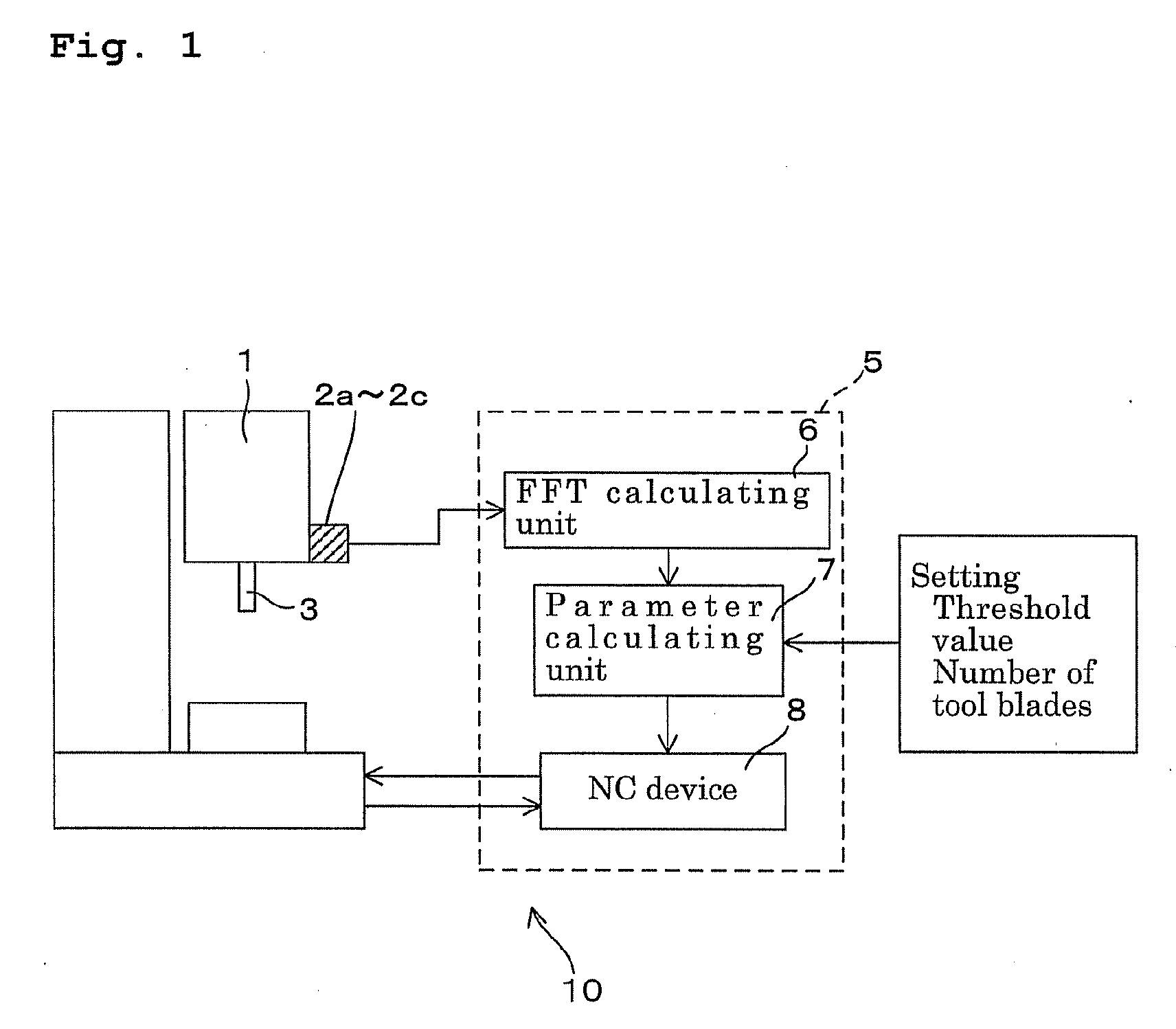
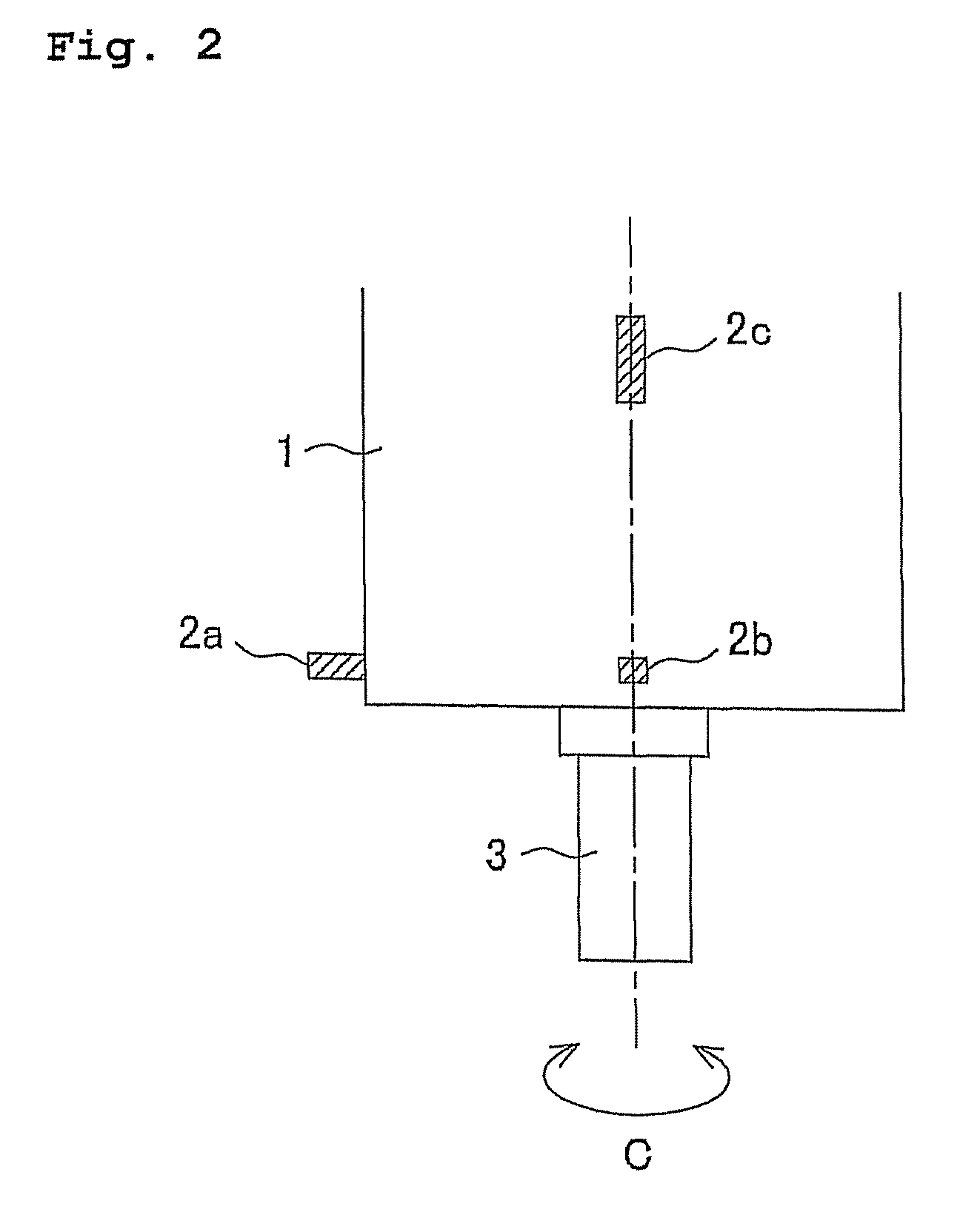
[0025]FIG. 1 is an explanatory diagram illustrating a block configuration of a vibration suppressing device 10. FIG. 2 is an explanatory diagram laterally illustrating a rotary shaft housing 1, which is subject to vibration suppression. FIG. 3 is an explanatory diagram illustrating the rotary shaft housing 1 in a shaft direction.

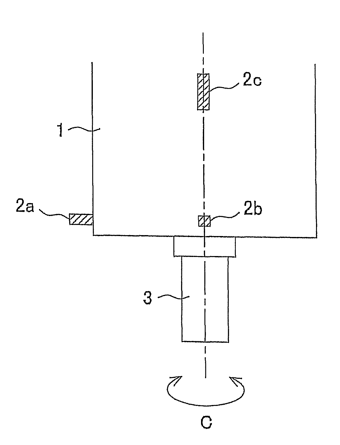
[0026]The vibration suppressing device 10 suppresses “chatter vibration” generated in a rotary shaft 3 rotatably provided around a C-axis put through the rotary shaft housing 1, and includes vibration sensors (detecting means) 2a to 2c for detecting time-domain vibrational accelerations generated in the rotating rotary shaft 3, and a control device (calculating means and rotation speed controlling means) 5 for controlling a rotation speed of the rotary shaft 3 on the basis of values detected by the vibration sensors 2a to 2c.

[0027]The vibration sensors 2a to 2c are attached to the rotary shaft housing 1 as illustrated in FIGS. 2 and 3, and one of the vibrat...

embodiment 2

[0041]Next, another embodiment of the present invention is described. Configurations of the vibration suppressing device and rotary shaft housing are the same as those in Embodiment 1, so that duplicate description of them is omitted. The suppression control of the “chatter vibration” in the control device 5 is described on the basis of the flowchart illustrated in FIG. 7.

[0042]First, in the FFT calculating unit 6, the Fourier analyses is performed regarding the time-domain vibrational accelerations continuously detected at the positions of the vibration sensors 2a to 2c during the rotation (S21). Then, the maximum acceleration as illustrated by Reference numeral 4 of FIG. 4 and its associated frequency (chatter frequency) are calculated (S22).

[0043]Next, in the parameter calculating unit 7, the maximum acceleration having been calculated in the above S22 and a predetermined threshold value having been preset are compared with each other (S23). When the maximum acceleration exceeds ...

embodiment 3

[0052]Referring to FIG. 8, in the FFT calculating unit 6, the Fourier analyses are first performed regarding the time-domain vibrational accelerations continuously detected at the positions of the vibration sensors 2a to 2c during the rotation (S31), and the maximum acceleration as illustrated by Reference numeral 4 of FIG. 4 and its associated frequency (chatter frequency) are calculated (S32).

[0053]Then, in the parameter calculating unit 7, the maximum acceleration having been calculated in the above S32 is compared with a predetermined threshold value having been preset (S33), and if the maximum acceleration exceeds the threshold value, the k-value and phase information are calculated in S34 on the basis of the chatter frequency, number of tool blades, and rotation speed of the rotary shaft 3 with use of the following calculating expressions (1) to (3), on the assumption that the chatter vibration to be suppressed is generated in the rotary shaft 3.

k′-value=60×Chatter frequency / (...


PUM

PropertyMeasurementUnit
time-domain vibrationaaaaaaaaaa
rotation speedaaaaaaaaaa
frequencyaaaaaaaaaa

Abstract

A vibration suppressing device and a vibration suppressing method that are capable of obtaining an accurate optimum rotation speed and shortening a time period from generation of chatter vibration to calculation of the optimum rotation speed are provided. The vibration suppressing device 10 includes: vibration sensors 2a to 2c for detecting time-domain vibrational accelerations of a rotary shaft 3 in rotation; and a control device 5 for calculating a chatter frequency and a frequency-domain vibrational acceleration of the rotary shaft 3 at the chatter frequency on the basis of the time-domain vibrational accelerations detected by the vibration sensors 2a to 2c, and when the calculated frequency-domain vibrational acceleration exceeds a predetermined threshold value, calculating an optimum rotation speed on the basis of a predetermined parameter, and rotating the rotary shaft 3 at the calculated optimum rotation speed.

Description

BACKGROUND OF THE INVENTION[0001]This application claims the benefit of Japanese Patent Application Numbers 2007-138164, 2007-138166 and 2007-138375 which were filed on May 24, 2007, the entirety of which is incorporated by reference.FIELD OF THE INVENTION[0002]The present invention relates to a vibration suppressing device and a vibration suppressing method for suppressing vibration generated during machining in a machine tool that performs the machining while rotating a tool or work.BACKGROUND ART[0003]There has conventionally been a machine tool, for example, where a work is supported by a rotatable main spindle and machined while a tool is being fed to the work. However, in the conventional machine, when a cutting depth in cutting machining is made larger than necessary, so-called “chatter vibration” is generated during the machining, resulting in deterioration in finishing accuracy of a machined surface. Particularly, “regenerative type chatter vibration” which is self-excited ...

Claims


Application Information

Patent Timeline
Patent Type & Authority Applications(United States)
IPC IPC(8): F16F7/10B23B47/00
CPCB23Q17/0976G05B19/404G05B2219/37435Y10T408/76Y10T409/30084Y10T409/304312Y10T409/303752Y10T408/23Y10T408/172Y10T83/849Y10T83/773Y10T83/086Y10T83/474
Inventor SUZUKI, NORIKAZUSHAMOTO, EIJIINAGAKI, HIROSHI
Owner OKUMA CORP
Why Eureka
Try Eureka