System and method for field calibration of flow meters

a flow meter and field calibration technology, applied in the direction of instruments, liquid/fluent solid measurement, testing/calibration for volume flow, etc., can solve the problems of cumbersome method, less precise flow rate measurement, and cost prohibitive removal of spool pieces or pipes for offsite calibration, so as to achieve accurate flow rate or velocity measurement, less complex, and cost-effective

Active Publication Date: 2009-01-08
BAKER HUGHES INC
View PDF6 Cites 35 Cited by
  • Summary
  • Abstract
  • Description
  • Claims
  • Application Information

AI Technical Summary

Benefits of technology

[0009]Embodiments of this invention provide cost-effective, less complex, and more precise calibration of flow meters in the field. Since transit times are principally a function

Problems solved by technology

Additionally, in many typical flow meters, erosion or contaminant deposits over time can cause the flow meter transducer signals to deteriorate, which can result in less precise flow rate measurements.
It is typically cost prohibitive to remove a spool piece or portion of a pipe for offsite calibration, because of the great expenditure of time and resources and resulting system down tim

Method used


Image

  • System and method for field calibration of flow meters
  • System and method for field calibration of flow meters
  • System and method for field calibration of flow meters

Examples


Embodiment Construction

[0036]Aside from the embodiment or embodiments disclosed below, this invention is capable of other embodiments and of being practiced or being carried out in various ways. Thus, it is to be understood that the invention is not limited in its application to the details of construction and the arrangements of components set forth in the following description or illustrated in the drawings. If only one embodiment is described herein, the claims hereof are not to be limited to that embodiment. Moreover, the claims hereof are not to be read restrictively unless there is clear and convincing evidence manifesting a certain exclusion, restriction, or disclaimer.

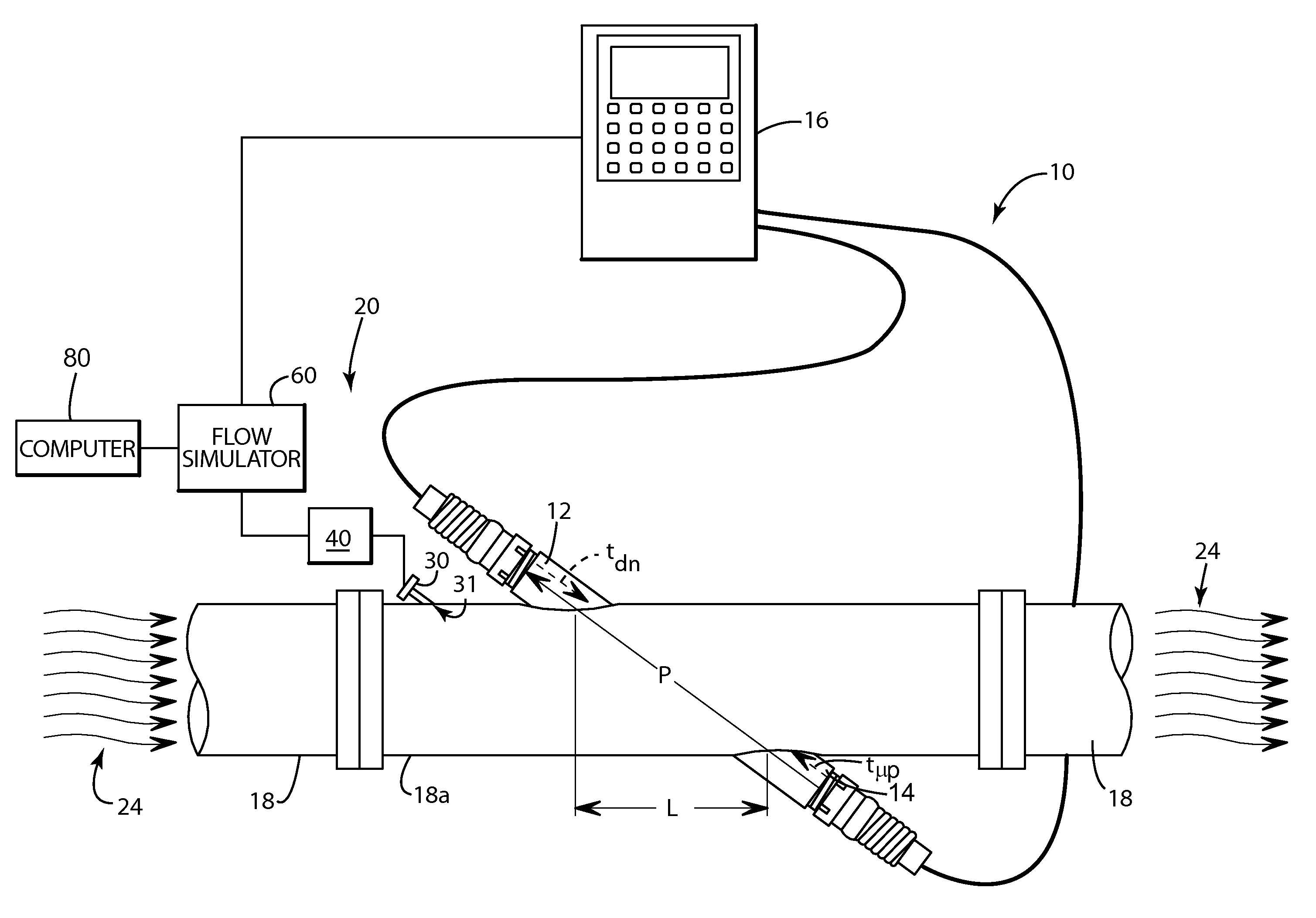
[0037]One typical flow meter 10, FIG. 1 includes transducers 12 and 14 and associated processing and electronics 16. Transducers 12 and 14 are shown on opposite sides of pipe or conduit 18, but in various flow meters the transducers may be on the same side of the pipe, or there may be more than two transducers. As shown, conduit 18 i...


PUM


Abstract

A calibration system for a flow meter includes a flow simulator, the flow simulator including a receiver configured to receive flow meter transducer signals from a flow meter. A simulation subsystem is configured to create simulated transit time signal pulses, and to transmit the simulated transit time signal pulses to the flow meter at preselected time intervals. A calibration subsystem is configured to receive from the flow meter a transit time differential value generated by the flow meter based on the simulated transit time signal pulses and output a calibration factor to the flow meter.

Description

FIELD OF THE INVENTION[0001]The embodiments of subject invention relate to a system and method for field calibration of flow meters, and in one example, field calibration of flare gas flow meters.BACKGROUND OF THE INVENTION[0002]Flow meters and flow meter systems are utilized to measure properties of fluids flowing in pipes or conduits. One particular property of interest is the flow rate or velocity of the fluid. Ultrasonic transducers are often employed to measure flow velocity based on the transit time of ultrasonic signals transmitted through the fluid.[0003]Typically, a flow meter measures flow velocity using two transducers which are located upstream and downstream from each other on a pipe or conduit. Each transducer transmits and receives in an alternating manner. Flow velocity is then computed as a function of the transit times of the ultrasonic signals both with and against the direction of flow, i.e. the difference between the upstream and downstream transit times. For ex...

Claims


Application Information

Patent Timeline
IPC IPC(8): G01F25/00G06F19/00
CPCG01F25/0007G01F1/668G01F25/10
Inventor AO, XIAOLEI S.TILDEN, JEFFREY
Owner BAKER HUGHES INC
Why Eureka
Try Eureka