Negative-camber-airfoil fuselage brake-induced differential type multi-rotor helicopter

A negative camber, multi-rotor technology, applied in the direction of rotorcraft, fuselage, motor vehicles, etc., can solve the problems of increased reaction time, low load capacity, difficult problems, etc., and achieve the effect of stable pitch control

Inactive Publication Date: 2020-02-14
江富余
View PDF0 Cites 0 Cited by
  • Summary
  • Abstract
  • Description
  • Claims
  • Application Information

AI Technical Summary

Problems solved by technology

However, when the rotor load increases, the reaction time for adjusting the motor speed to change the rotor speed increases, which affects the handling performance. Therefore, the load capacity of conventional multi-rotor helicopters is not high. When using the engine to drive each rotor, the throttle delay also makes the adjustment of the engine The reaction time of changing the speed of the rotor speed increases, and it is difficult for a quadcopter with a constant pitch to use a fuel engine to drive the rotor

Method used


Image

  • Negative-camber-airfoil fuselage brake-induced differential type multi-rotor helicopter
  • Negative-camber-airfoil fuselage brake-induced differential type multi-rotor helicopter
  • Negative-camber-airfoil fuselage brake-induced differential type multi-rotor helicopter

Examples


Embodiment Construction

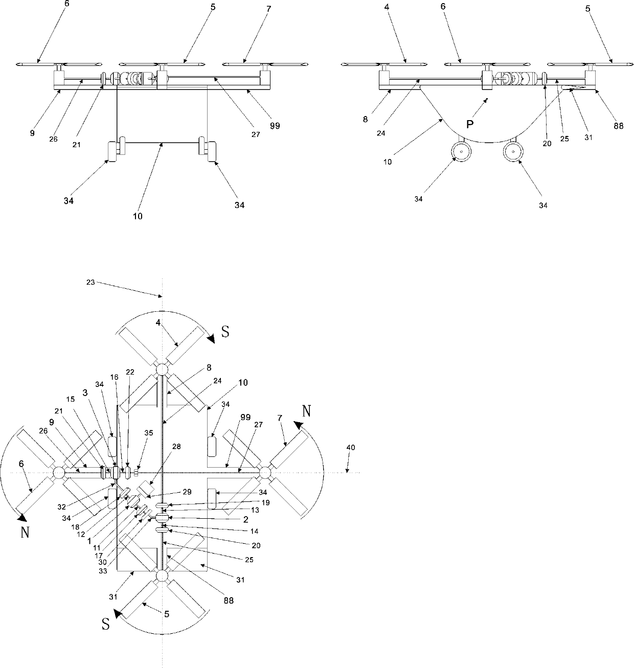
[0111] figure 1 In the shown embodiment, the four rotors adopt a cross-shaped layout, and the front cantilever beam (8) is set forward on the front top center longitudinal line (23) of the negative camber airfoil fuselage (10), and the top of the front cantilever beam (8) Set the front rotor (4), set the rear cantilever beam (88) backward along the top center longitudinal line (23) behind the negative camber airfoil fuselage (10), and set the rear rotor (5) at the top of the rear cantilever beam (88) , the line connecting the rotation centers of the front and rear rotors overlaps with the longitudinal line (23) at the top center of the negative camber airfoil fuselage; The top of the left cantilever beam (9) is provided with the left rotor (6), the right cantilever beam (99) is provided on the right side of the top central transverse line (40) of the negative camber airfoil fuselage (10), and the top of the right cantilever beam (99) is provided with the right cantilever beam ...


PUM


Abstract

The invention discloses a negative-camber-airfoil fuselage brake-induced differential type multi-rotor helicopter. A fuselage adopts a negative camber airfoil, a flap is arranged to change the camberof the airfoil fuselage, four rotor wings are arranged at the top of the fuselage, an engine drives a first differential through a gearbox, the first differential drives a second differential and a third differential, a third rotating shaft of the second differential is connected with a gear inverted rotating device to change steering and then drives the left rear rotor wing, a fourth rotating shaft of the second differential drives the right rear rotor wing, a sixth rotating shaft of the third differential is connected with the gear inverted rotating device to change steering and then drivesthe right front rotor wing, a fifth rotating shaft drives the left front rotor wing, each output rotating shaft of each differential is provided with a brake, the rotating speed of one output shaft ofone differential is controlled by the brake to induce the other output shaft of the differential to change the rotating speed, meanwhile, the rotating speed of a group of rotor wings is changed, therotating speed changing combination of the rotor wings is changed through different brake combined braking modes, so that the flight attitude is manipulated, and the helicopter is suitable for occasions that the helicopter needs to take off and hover anytime and anywhere.

Description

technical field [0001] The invention relates to a multi-rotor helicopter with a negative camber airfoil fuselage brake-induced differential speed which adopts multi-rotor vertical lifting, hovering, front-back, left-right, and left-right flight independently of the airport. Background technique [0002] At present, the known successful method of multi-rotor helicopters that can realize vertical lift, hovering, front-back, left-right, and left-right flight is a quadrotor helicopter. Each rotor is driven by an independent motor. By changing the relative speed of different motors, the lift of the corresponding rotor is changed. , to control the pitch, roll and heading of the multi-rotor helicopter, and the quad-rotor helicopter has the advantages of simple structure and high reliability because the rotor adopts a constant pitch. However, when the rotor load increases, the reaction time for adjusting the motor speed to change the rotor speed increases, which affects the handling...

Claims


Application Information

Patent Timeline
Patent Type & Authority Applications(China)
IPC IPC(8): B64C27/32B64C27/08B64C27/12B64C1/00
CPCB64C1/00B64C27/08B64C27/12B64C27/32
Inventor 江富余
Owner 江富余
Why Eureka
Try Eureka