Rotor rotating structure design of tilt rotor aircraft

A technology of tilting rotor and rotating structure, applied in the direction of rotorcraft, aircraft, motor vehicle, etc., can solve the problems of high technical difficulty, aerodynamic interference, etc., and achieve the effect of simple principle, flexible rotation movement, and large load capacity

Inactive Publication Date: 2018-04-13
李宁
View PDF4 Cites 0 Cited by
  • Summary
  • Abstract
  • Description
  • Claims
  • Application Information

AI Technical Summary

Problems solved by technology

High technical difficulty: since the tiltrotor has both rotor and wing, and the rotor needs to be tilted from the vertical position to the horizontal position or from the horizontal position to the vertical position, the determination of the aerodynamic characteristics during the rotor tilting process; Aerodynamic interference between wing, rotor / rotor, rotor / body; structural design; dynamic analysis of rotor during tilting, rotor / wing coupling dynamic load and stability issues; control technology and control system dynamics Many technical difficulties have been encountered in design and other aspects

Method used


Image

  • Rotor rotating structure design of tilt rotor aircraft
  • Rotor rotating structure design of tilt rotor aircraft

Examples


Embodiment Construction

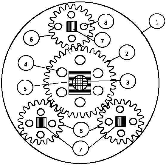
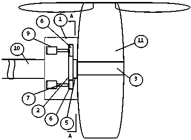
[0017] The whole device structure includes the following parts: 1. device shell, 2. main gear, 3. connecting shaft, 4. main gear weight reduction hole, 5. main gear and rotor connecting part, 6. auxiliary gear, 7. auxiliary gear rotation shaft, 8. auxiliary gear weight reduction hole , 9 motors, 10 device fixed structures, which are part of the wing, and 11 rotor structures.

[0018] The structure of the invention is fixed by 10 devices, that is, the end of the wing of the aircraft is connected to the aircraft. The gear part of the whole structure is tightly installed inside the housing of the device 1, and the housing of the device 1 is fixed on the fixing structure of the device 10. 2 main gears and 6 auxiliary gears each have 4 main gear lightening holes and 8 auxiliary gear lightening holes to reduce the weight of the gear part. The device is connected to the rotor through 5 main gears, welded or bolted, and the 2 main gears are fixed to the 11 rotor structure. 11 The ro...


PUM


Abstract

The invention relates to rotor rotating structure design of a tilt rotor aircraft. The tilt rotor aircraft has the performance advantages of high speed, low noise, long voyage, large load capacity, low fuel consumption rate, low transport cost and small vibration. Through a gear combination structure, the angles between rotors and an aircraft fuselage are changed, and thus the rotors are tilted from the vertical position to the horizontal position or from the horizontal position to the vertical position.

Description

technical field [0001] The invention relates to a rotor rotation structure design of a tilt rotor aircraft. Background technique [0002] Tilt-rotor aircraft, represented by the American Osprey tilt-rotor aircraft, V-22, the code name of the Osprey tilt-rotor aircraft, was developed in the 1980s, and the first flight was successful on March 19, 1989. After the testing, modification and verification work. He entered service in the U.S. Air Force on November 16, 2006, served in the U.S. Marine Corps in 2007, and went to Afghanistan for actual combat deployment in the same year. [0003] But the two rotatable engines at the wingtips drive the two rotors. In the fixed-wing state, the V-22 seems to be an aircraft with two oversized propellers on the wingtips on both sides; It seems to be a helicopter with two smaller rotors, so that it has the vertical lift capability of a helicopter, but it also has the advantages of high speed, long range and low fuel consumption of a fixed-w...

Claims


Application Information

Patent Timeline
Patent Type & Authority Applications(China)
IPC IPC(8): B64C27/52
CPCB64C27/52
Inventor 不公告发明人
Owner 李宁
Why Eureka
Try Eureka