
Dedicated self-aligning mechanism for lens and concentricity adjusting device employing same
A lens and centering technology, applied in installation, optics, instruments, etc., can solve problems such as high cost, inability to guarantee adjustment accuracy, inconvenient adjustment operation, etc., and achieve less error influencing factors, simple and quick adjustment, and convenient concentricity adjustment Effect
- Summary
- Abstract
- Description
- Claims
- Application Information
AI Technical Summary
Problems solved by technology
Method used
Image

Examples
Embodiment
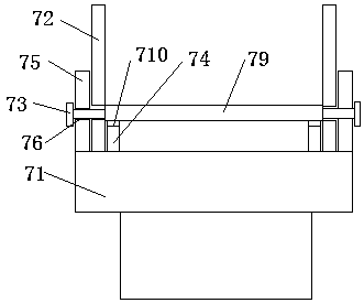
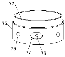
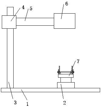
[0022] A lens-specific centering mechanism, such as figure 1 and figure 2 , comprising a support 71, a lens barrel 72 and a number of positioning bolts 73, the top surface of the support 71 is provided with an annular inner frame 74 and an annular outer frame 75, and an annular groove is formed between the annular inner frame 74 and the annular outer frame 75, and in the annular groove The end portion of the lens barrel 72 is provided, the top surface of the annular inner frame 74 is provided with a lens 79, and the lens 79 is arranged in the lens barrel 72, the diameter of the lens 79 is greater than the diameter of the annular inner frame 74, and the annular outer frame 75 is evenly arranged around A plurality of positioning holes 76, the positioning holes 1 76 are provided with internal threads, the lens barrel 72 is evenly surrounded by a number of positioning holes 2, the positioning holes 1 76 are correspondingly arranged with the positioning holes 2 one by one, and the...
PUM
 Abstract
Description
Claims
Application Information