
Dehumidification and drainage cable trench

A technology for cable trenches and drains, which is applied in cable installation, ground cable installation, electrical components, etc. It can solve problems such as cable erosion, increase safety hazards, and user impact, so as to eliminate moisture, ensure electricity safety, and extend The effect of service life

Inactive Publication Date: 2018-04-13
江苏新金牛线缆有限公司
View PDF0 Cites 4 Cited by
  • Summary
  • Abstract
  • Description
  • Claims
  • Application Information

AI Technical Summary

Problems solved by technology

[0002]Cable trench is an underground dedicated channel for laying cables. It is mostly used for laying substations or urban lines. Traditional cable trenches are made of cement, although cement The strength of the cable trench is good, but because it is laid underground, the cement structure is easy to be affected by moisture. When the humidity in the cable well is too high, the cable will be corroded, resulting in short circuit and other adverse conditions, which will increase safety hazards and affect normal electricity consumption. Provide users with a great impact

Method used


Image

  • Dehumidification and drainage cable trench
  • Dehumidification and drainage cable trench
  • Dehumidification and drainage cable trench

Examples


Embodiment Construction

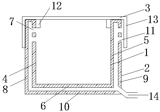
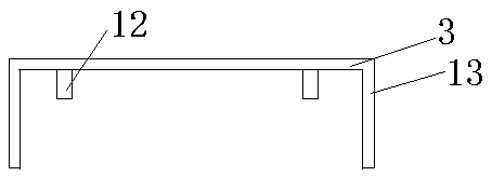
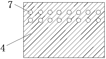
[0015] Attached below Figure 1-4 The structure, principle and working process of the present invention will be further described with specific embodiments, but the protection scope of the present invention is not limited thereto.

[0016] It should be noted that the embodiments provided by the present invention are only for effectively explaining the technical characteristics of the present invention, and the positioning words such as left, right, upper end, and lower end are only for better understanding of the embodiments of the present invention. The description should not be regarded as a limitation on the technical solution of the present invention.

[0017] A cable trench for dehumidification and drainage, including an inner tank 1, an outer tank 2 and a cover plate 3, the inner tank 1, the outer tank 2 and the cover plate 3 are all made of cement, and the inner tank 1 includes the left side of the inner tank Riser 4, inner tank right side vertical plate 5 and inner ta...


PUM


Abstract

The invention provides a dehumidification and drainage cable trench, which includes an inner groove, an outer groove and a cover plate. The inner groove includes a left vertical plate of the inner groove, a right vertical plate of the inner groove and a bottom plate of the inner groove. The left vertical plate, the right vertical plate of the outer tank and the bottom plate of the outer tank form a hollow circuit between the inner tank and the outer tank, and two rows of circular The inner exhaust holes are also provided with two rows of outer exhaust holes at the upper position of the vertical plate on the right side of the outer tank corresponding to the height of the inner exhaust holes; one piece is extended at the edges of both sides of the cover plate. As for the side plate, a drain is opened at the bottom end of the vertical plate on the right side of the outer tank. Beneficial effects are: the design increases the air circulation in the cable trench and effectively removes moisture. The design of the side plate prevents rainwater from entering the cable trench from the vent hole. The outlet will flow out in time, and the cable trench will always be kept dry to ensure the safety of electricity use.

Description

technical field [0001] The invention relates to the field of tunnels and underground engineering, in particular to a dehumidification and drainage cable trench structure. Background technique [0002] The cable trench is an underground special channel for laying cables. It is mostly used for the laying of substations or urban lines. The traditional cable trenches are made of cement. Although the cable trench made of cement has good strength, because it is laid underground, cement The structure is easy to get damp, and when the humidity in the cable well is too high, the cable will be corroded, resulting in short circuit and other adverse conditions, increasing safety hazards, affecting normal power consumption, and greatly affecting the supply of users. Contents of the invention [0003] The purpose of the present invention is to provide a dehumidification and drainage cable trench, which can effectively solve the problem of ventilation and dehumidification in the cable tr...

Claims


Application Information

Patent Timeline
IPC IPC(8): H02G9/02
CPCH02G9/025
Inventor 凌建良
Owner 江苏新金牛线缆有限公司
Features
  • Generate Ideas
  • Intellectual Property
  • Life Sciences
  • Materials
  • Tech Scout
  • Unparalleled Data Quality
  • Higher Quality Content
  • 60% Fewer Hallucinations
Learn More