Test-tube rack

A test tube rack and test tube technology, which is applied to test tube holders/clamps, laboratory utensils, etc., can solve the problems of inability to accurately position the test tube, unable to hold the test tube stably, and the compatibility range is small, and achieves low processing and manufacturing costs and manufacturing costs. Inexpensive, compatible with a wide range of effects

Inactive Publication Date: 2018-04-17
MGI TECH CO LTD
View PDF5 Cites 8 Cited by
  • Summary
  • Abstract
  • Description
  • Claims
  • Application Information

AI Technical Summary

Problems solved by technology

[0009] The purpose of the present invention is to overcome the defects of the prior art, solve the problems of the existing test tube racks such as small compatible range, complicated structure, inability to accurately position the test tubes, and incapable of stably clamping the test tubes. A test tube rack is provided, which includes a main body, the The main body is provided with a jack for inserting a test tube, and the test tube rack also includes:

Method used


Image

  • Test-tube rack
  • Test-tube rack
  • Test-tube rack

Examples


Embodiment Construction

[0047] In order to make the object, technical solution and advantages of the present invention clearer, the present invention will be further described in detail below in conjunction with the accompanying drawings and embodiments. It should be understood that the specific embodiments described here are only used to explain the present invention, not to limit the present invention.

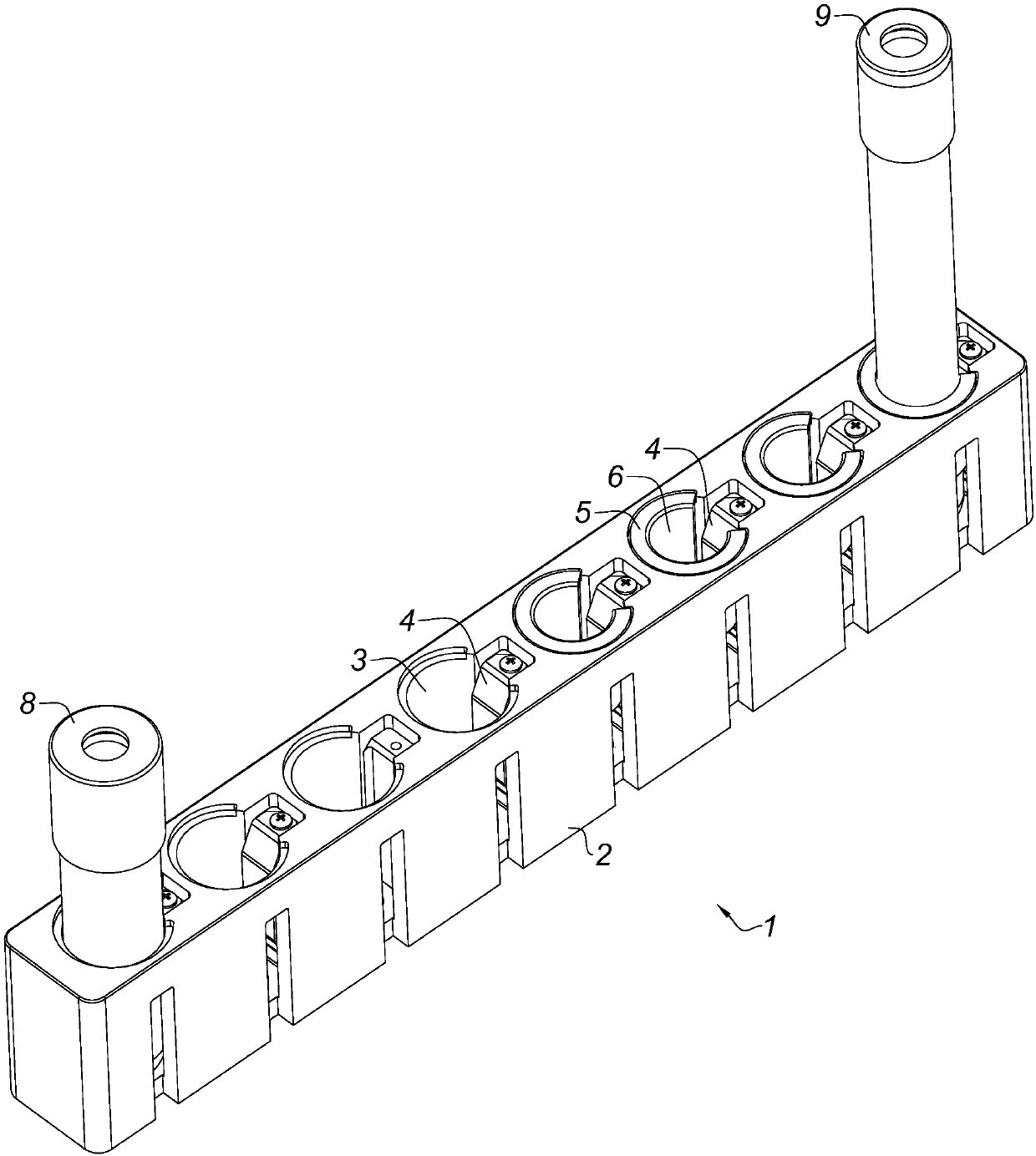
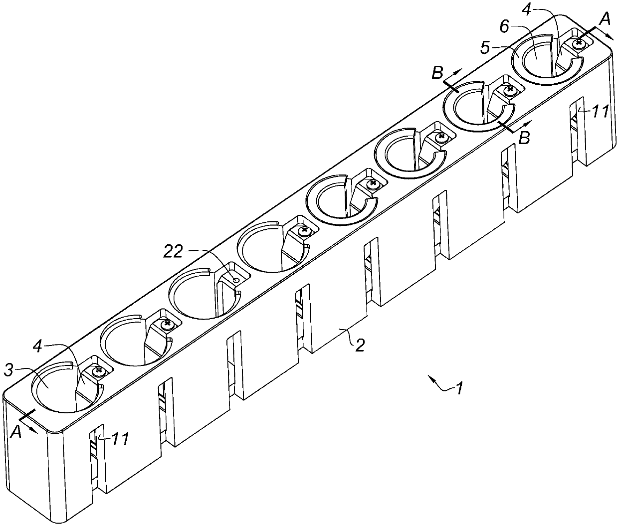
[0048] The test tube rack provided by the present invention can have multiple implementations. For ease of understanding, the following examples use one of the implementations as the main line of description. Figures 1 to 12What is shown is the test tube rack and some parts described in the main line; when describing some technical features of the main line, some alternative solutions of the technical features are interspersed as branches. Since these alternative solutions can be clearly expressed in words, Therefore, no additional drawings are provided for illustration.

[0049] see Figure 1-Fi...


PUM


Abstract

The invention belongs to the technical field of biochemical experiment auxiliary appliances and provides a test-tube rack in order to solve the problems that an existing test-tube rack is small in compatible range and complicated in structure, cannot position test tubes accurately and cannot clamp the test tubes stably and the like. The test-tube rack comprises a main body, wherein inserting holesallowing insertion of the test tubes are formed in the main body; the test-tube rack further comprises elastic pieces and adapters, the elastic pieces are arranged in the inserting holes and can supply elastic pressure to the test tubes, the adapters are inserted in the inserting holes and provided with through holes allowing insertion of the test tubes, each adapter is further provided with a notch yielding to the corresponding elastic piece, and the elastic piece can penetrate through the notch to supply elastic pressure to the corresponding test tube. With combination of the adapters and the elastic pieces, the test-tube rack can load and position the test tubes stably and accurately; besides, the test-tube rack requires a few parts and is simple in structure, the adapters can be processed into various sizes, various test tubes can be compatible by selecting the adapters with proper sizes, the operation is easy, flexibility is quite high, and the manufacturing cost of the test-tuberack is low.

Description

technical field [0001] The invention relates to a biochemical experiment auxiliary equipment, in particular to a test tube rack. Background technique [0002] Commonly used test tube racks are provided with jacks for test tube insertion, and the size of the jacks is fixed. Different jacks can only be inserted into test tubes of corresponding sizes, and their compatibility is very low. Although a test tube rack can be provided with multiple jacks of different sizes, its compatible range is still very limited. In order to facilitate the insertion and removal of the test tube, the size of the hole is generally slightly larger than the diameter of the test tube, and the inner wall of the hole cannot completely hold the test tube tightly, which means that the test tube rack cannot be subjected to violent vibrations, otherwise the test tube may fall out of the hole. Further, since the insertion holes cannot be fully matched with the test tubes, the test tubes cannot be fixed on t...

Claims


Application Information

Patent Timeline
Patent Type & Authority Applications(China)
IPC IPC(8): B01L9/06
CPCB01L9/06B01L2200/023
Inventor 吴文昊邓建中高建东彭美超丁盛李景
Owner MGI TECH CO LTD
Why Eureka
Try Eureka