Floating-type air pressure angle-fixed double-clamp vise structure

A floating vise technology, applied in the vise field, can solve the problems of stress concentration, reduced service life, slow processing speed, etc., and achieve the best processing precision, ensure the service life, and the best clamping force.

Inactive Publication Date: 2018-04-17
HOMGE MACHINERY IND
View PDF0 Cites 0 Cited by
  • Summary
  • Abstract
  • Description
  • Claims
  • Application Information

AI Technical Summary

Problems solved by technology

[0003] However, this vise structure can only hold one workpiece at a time, not only the processing speed is slow, but also the processing efficiency is limited. Moreover, the installation position of the pressure cylinder of this conventional structure is not designed to be waterproof, and the cutting fluid is easy to seep into the body, causing pressure The cylinder is damaged and its service life is reduced. In addition, the lead screw is only supported at one end, and the other end is in a suspended state, and the supporting force becomes poor, which easily deforms the lead screw. Furthermore, the top of the swing block has a concave gap, which is likely to cause stress Concentration, which makes it prone to breakage, therefore, the conventional knowledge has various deficiencies, and it is necessary to further improve it

Method used


Image

  • Floating-type air pressure angle-fixed double-clamp vise structure
  • Floating-type air pressure angle-fixed double-clamp vise structure
  • Floating-type air pressure angle-fixed double-clamp vise structure

Examples


Embodiment Construction

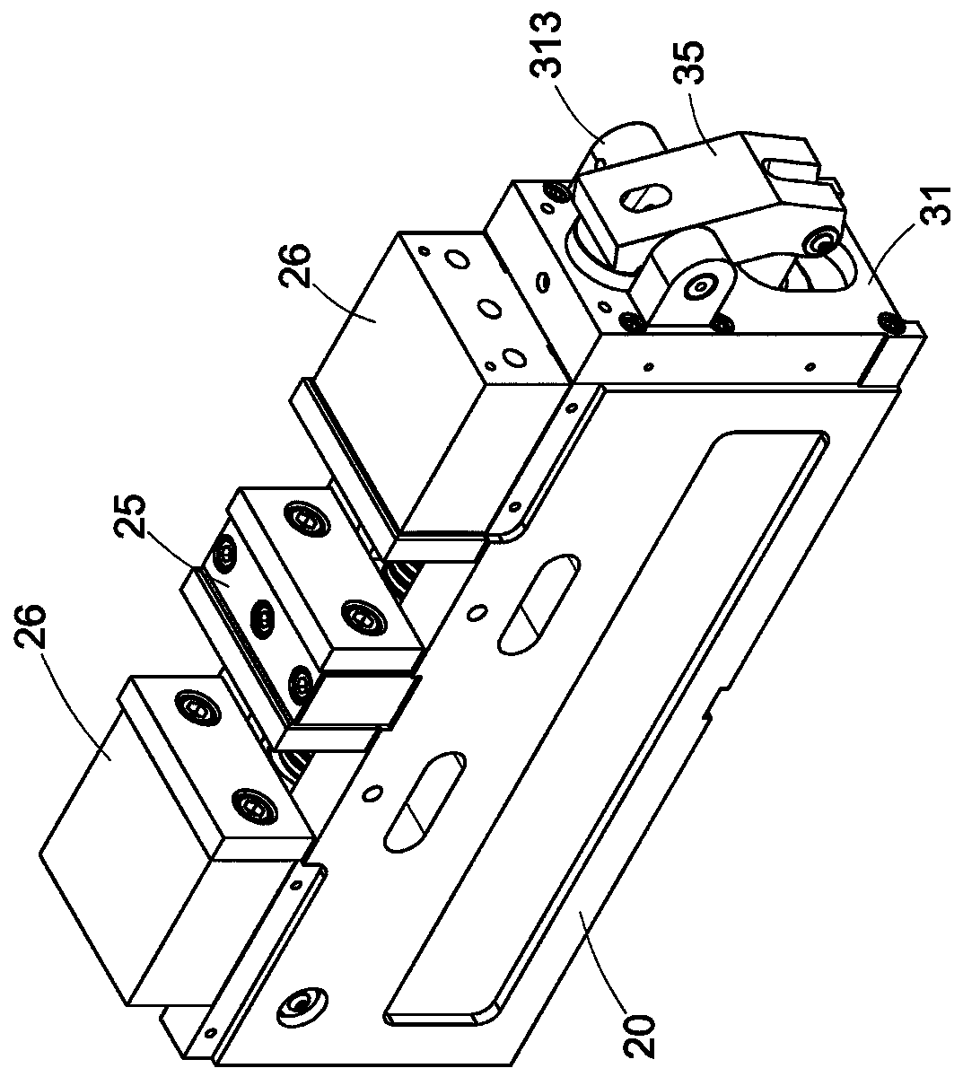
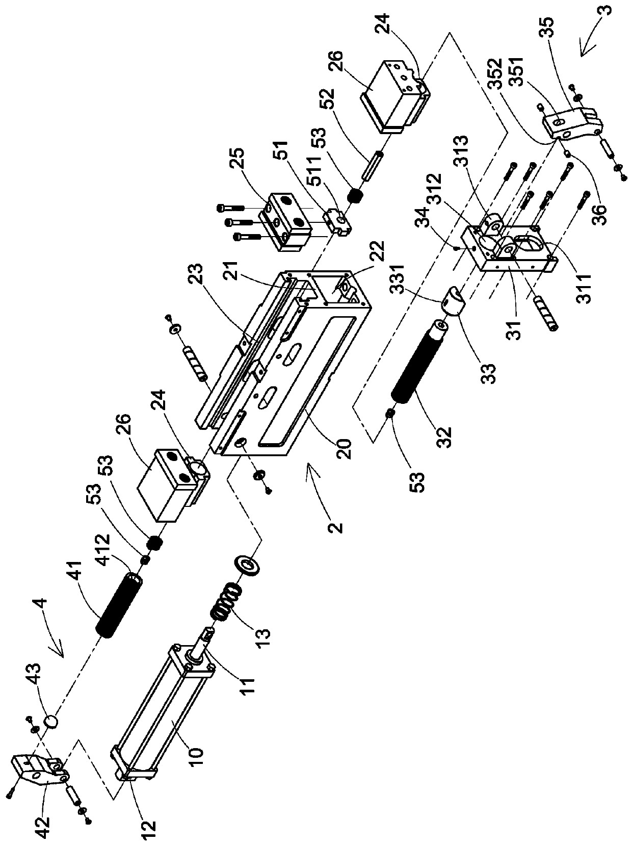
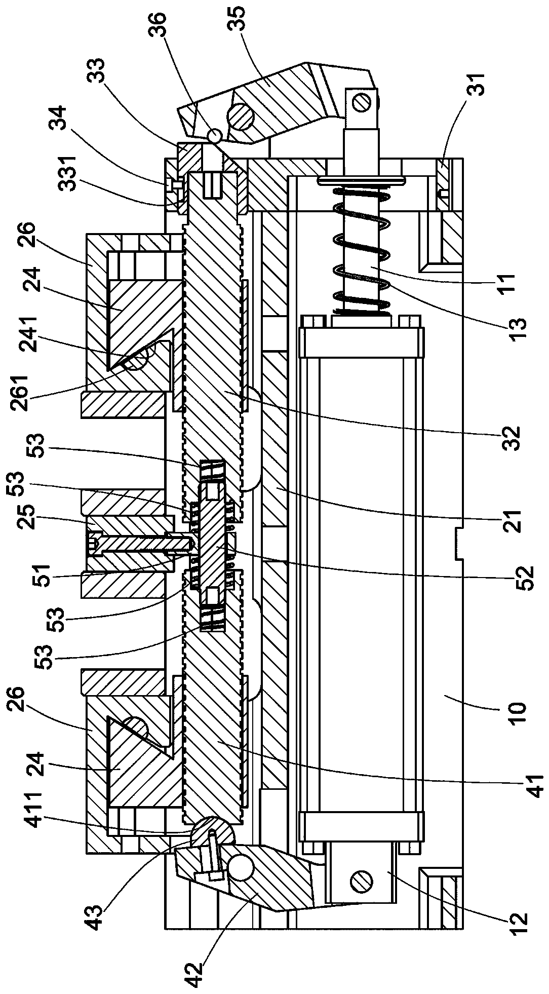
[0048] First, please refer to Figure 1 to Figure 5 As shown, the present invention is a floating air pressure angle fixed double clamp vise structure, which includes:

[0049] A pressure cylinder 10, the pressure cylinder 10 has a first push rod 11 and a second push rod 12;

[0050] A vise unit 2, the vise unit 2 has a body 20, a partition wall 21 is arranged laterally near the middle of the body 20, and the bottom surface of the partition wall 21 has an accommodating space 22 for the pressure cylinder 10 , and the relative setting position of the inner edge surface of the top surface of the partition wall 21 is provided with a guide rail 23 respectively. A fixed jaw 25 is fixed at the central position of the top surface of the body 20, and a movable jaw 26 with a pressing bar 261 is respectively installed on the two sides of the top surface of the main body 20 located at the fixed jaw 25, so that each pressing bar 261 is respectively pressed by the pressing inclined surface...


PUM


Abstract

The invention discloses a floating air pressure angle fixed double-clamp vise structure, which comprises a pressure cylinder, a vise unit, a first transmission unit, a second transmission unit and a connecting structure; the body of the vise unit is arranged A partition wall, a fixed jaw is fixed on the top surface of the body, and a movable jaw is respectively installed on the two sides of the fixed jaw on the top surface of the body, the linkage block of the first transmission unit is locked on one side of the body, and the first transmission unit The swing block near the top is pivoted with the linkage block, and the bottom end of the swing block of the first transmission unit is pivoted with the first push rod of the pressure cylinder, and the second transmission unit is installed on one side of the body. A pressure block is fixed on one side of the swing block of the transmission unit, and the bottom end of the swing block of the second transmission unit is pivoted to the second push rod of the pressure cylinder, and the connecting block of the connecting structure is installed in the body, thereby, Two workpieces can be clamped at one time, not only the processing speed is fast, but also has better clamping force, so that it has better processing precision.

Description

technical field [0001] The invention relates to the technical field of vises, in particular to a floating air pressure angle-fixed double-clamp vise structure. Background technique [0002] China Taiwan announcement number M285422 is an angle-fixed air hydraulic vise, which mainly includes a body with a fixed jaw at one end, a pressure cylinder, a lead screw, a movable jaw and a force that is pushed against the swing by the pressure cylinder. A tightening device; wherein, the tightening device is arranged on the outer side of the front end of the body, and the bottom end of the swing block arranged on the front seat of the body is pivotally connected with the push rod of the pressure cylinder protruding from the front seat of the body, so that the swing block produces a deflection action, and then The upper end is linked with the lead screw to produce a moderate action to clamp and release. [0003] However, this vise structure can only hold one workpiece at a time, not onl...

Claims


Application Information

Patent Timeline
Patent Type & Authority Applications(China)
IPC IPC(8): B25B1/18B25B1/02B25B1/10B25B1/24
CPCB25B1/18B25B1/02B25B1/10B25B1/24
Inventor 林溪水
Owner HOMGE MACHINERY IND
Why Eureka
Try Eureka