Cross shaft type electric transmission track-laying vehicle differential traveling device driven by two motors

A dual-motor drive and traveling device technology, applied in the transmission device, vehicle components, non-deflectable wheel steering, etc., can solve the problems of complex structure, high maintenance cost and high cost of hydraulic system, and achieve simple control, simple structure, and layout reasonable effect

Active Publication Date: 2018-04-17
JILIN UNIV
View PDF7 Cites 3 Cited by
  • Summary
  • Abstract
  • Description
  • Claims
  • Application Information

AI Technical Summary

Problems solved by technology

[0003] The purpose of the present invention is to solve the problems of complex structure, high cost and high maintenance cost of the hydraulic system in the electric transmission or hybrid crawler vehicles driven by dual power flows.

Method used


Image

  • Cross shaft type electric transmission track-laying vehicle differential traveling device driven by two motors
  • Cross shaft type electric transmission track-laying vehicle differential traveling device driven by two motors
  • Cross shaft type electric transmission track-laying vehicle differential traveling device driven by two motors

Examples


Embodiment Construction

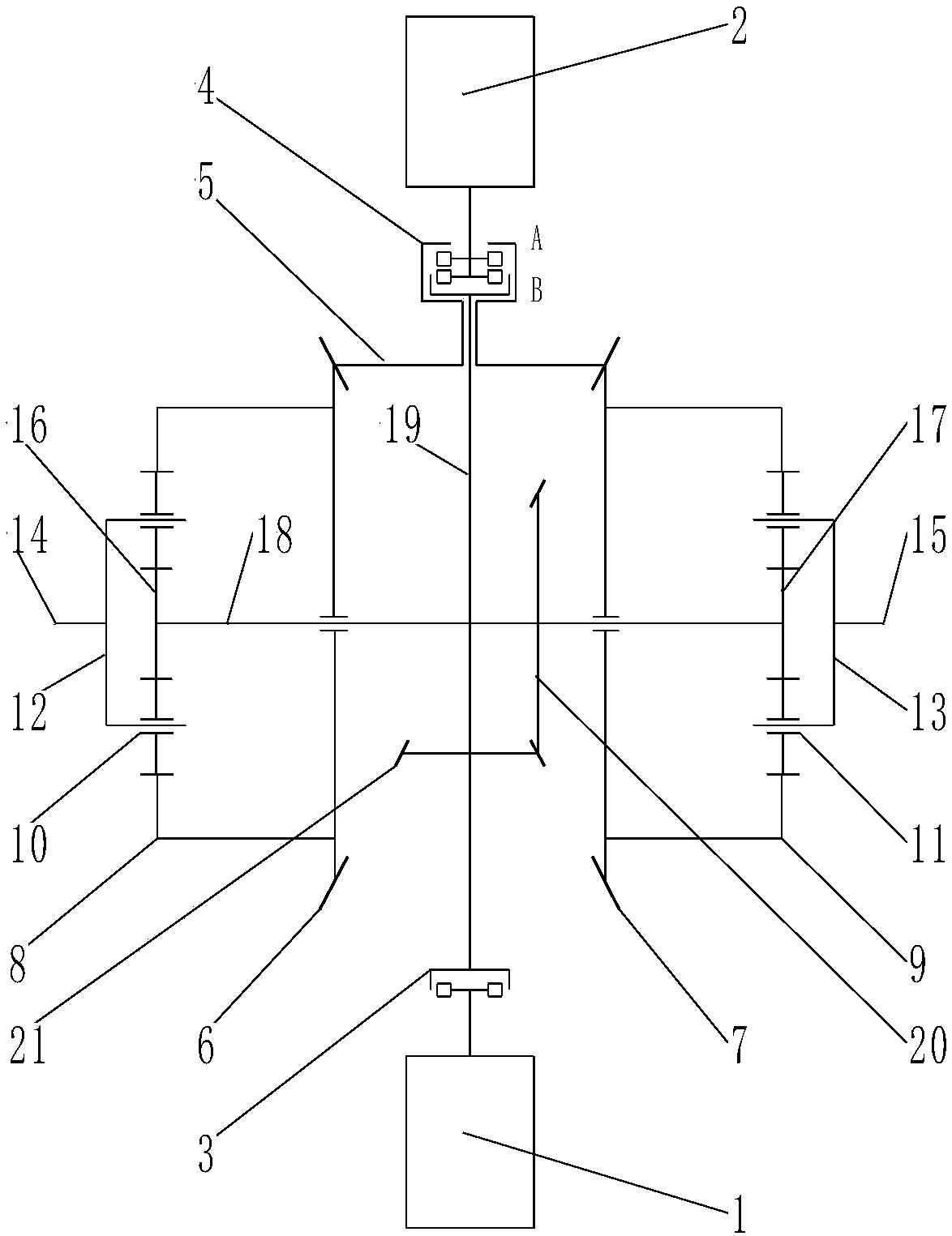
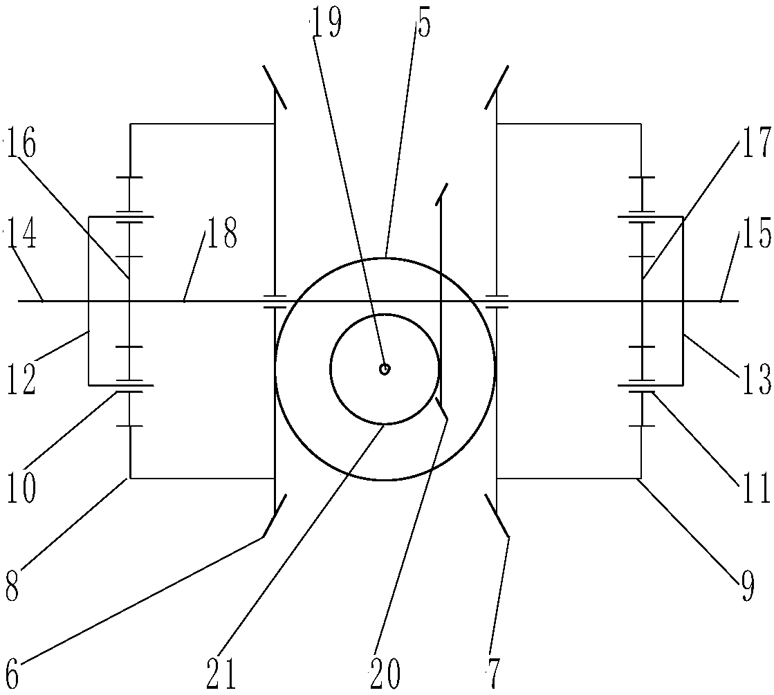
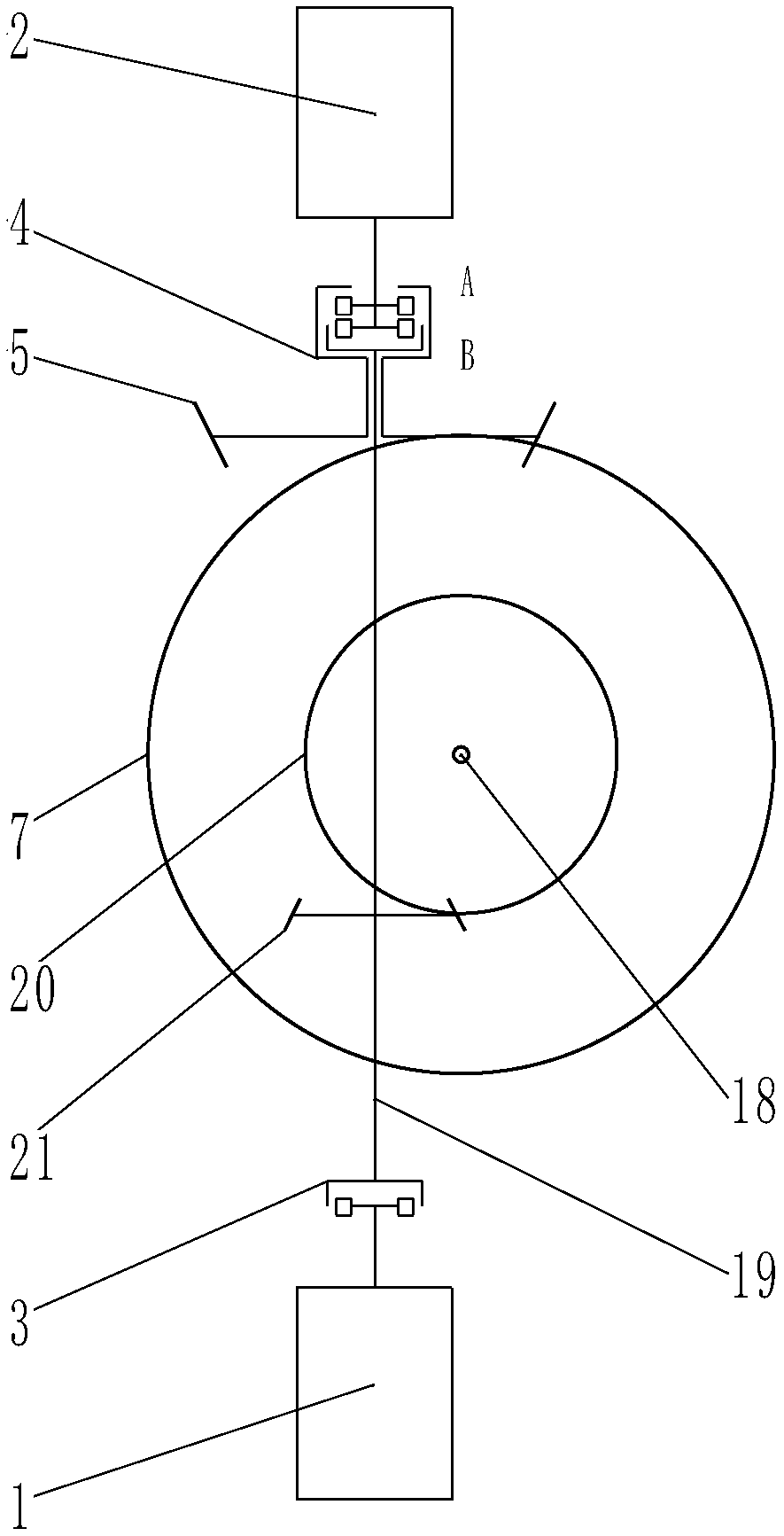
[0021] The running states of tracked vehicles are divided into straight line running, turning in situ and turning. In the present invention, according to the control to the clutch connection state, the above three running states of tracked vehicles can be realized. Different driving speeds and turning radii of tracked vehicles can be realized through the control.

[0022] Referring to Table 1, O is for clutch connection, and X is for clutch disconnection.

[0023] When the one-way clutch 3 was connected, and the two-way clutch 4A end and the B end were all in the disconnected state, the driving bevel gear 5 must be fixed, and now the tracked vehicle was a straight-line running state driven by a single motor (drive motor 1). The power is generated by the drive motor 1 and transmitted to the sun gear I16 and sun gear II17 through the main transmission device. At this time, the ring gear I8 and the ring gear II9 are in a fixed state, so the power passes through the planetary carr...


PUM


Abstract

The invention relates to a cross shaft type electric transmission track-laying vehicle differential traveling device driven by two motors and belongs to the technical field of engineering machinery. The device comprises a driving motor, a steering motor, a two-way clutch, a one-way clutch, a main transmission mechanism, a differential mechanism and two power coupling mechanisms. Bevel gears of themain transmission mechanism and the differential mechanism are all double-curved-surface bevel gears, driving bevel gears are identical in offset direction and concentric, the driving motor is connected with a main transmission shaft through the one-way clutch, and the steering motor is connected with the main transmission shaft and the driving bevel gear of the differential mechanism through thetwo-way clutch. The steering motor and the driving motor are controlled by the two-way clutch to drive a track-laying vehicle at the same time for linear traveling, pivot steering or steering traveling. Both the driving motor and the steering motor adopt frequency-variable control technology, so that turning radius and power distribution of the track-laying vehicle are controlled accurately. Thedevice is simple in structure, reasonable in arrangement, few in parts, stable in transmission, high in transmission efficiency and simple to control.

Description

technical field [0001] The invention belongs to the technical field of engineering machinery, and in particular relates to a dual-motor-driven cross-axle electric transmission crawler vehicle differential travel device. Background technique [0002] In the existing tracked vehicle walking system, the steering mechanism of the tracked vehicle is mainly a steering clutch and brake with a single power flow in the rear axle of the walking device. When the tracked vehicle goes straight, the clutches on both sides are in the engaged state. When steering is required, the clutch is disconnected to lose power on one side of the track or the brake is used to brake one side of the track to achieve the purpose of turning. At this time, the vehicle has only one R=0.5B fixed turning radius and cannot achieve variable turning radius and turning. At the same time, the steering of the tracked vehicle relies on the friction between the track and the ground, which not only causes serious power...

Claims


Application Information

Patent Timeline
Patent Type & Authority Applications(China)
IPC IPC(8): B62D11/14F16H37/08
CPCB62D11/14F16H37/0813F16H37/082
Inventor 王继新孔维康孔德文
Owner JILIN UNIV
Why Eureka
Try Eureka