
Protection and safety relay device of magnetically opened and closed door

A safety relay and magnetic switch technology, applied in transportation and packaging, elevators in buildings, etc., can solve problems such as hidden dangers of magnetic switch doors, user's magnetic switch door pinch, user's health hazards, etc., and achieves good mute effect. , Improve the effect of user experience

Pending Publication Date: 2018-04-17
WUXI UNITE ENERGY TECH CO LTD
View PDF0 Cites 0 Cited by
  • Summary
  • Abstract
  • Description
  • Claims
  • Application Information

AI Technical Summary

Problems solved by technology

[0004] The purpose of the present invention is to provide a magnetic switch door protection and safety relay device to solve the problem that the traditional magnetic switch door proposed in the background technology has a relatively simple structure, which leads to monitoring blind spots in the use of the magnetic switch door. Be careful to enter the monitoring blind area of ​​the magnetic switch door. The user is easily caught by the magnetic switch door, which is harmful to the user's health. Therefore, the use of the traditional magnetic switch door has potential safety hazards. Secondly, the traditional magnetic switch door is due to lack The corresponding sound insulation structure leads to the general sound insulation effect of the magnetic switch door. When the magnetic switch door is closed, the user can still hear the external noise, which affects the user's experience with the magnetic switch door.

Method used


Image

  • Protection and safety relay device of magnetically opened and closed door
  • Protection and safety relay device of magnetically opened and closed door
  • Protection and safety relay device of magnetically opened and closed door

Examples


Embodiment Construction

[0021] The following will clearly and completely describe the technical solutions in the embodiments of the present invention with reference to the accompanying drawings in the embodiments of the present invention. Obviously, the described embodiments are only some, not all, embodiments of the present invention. Based on the embodiments of the present invention, all other embodiments obtained by persons of ordinary skill in the art without making creative efforts belong to the protection scope of the present invention.

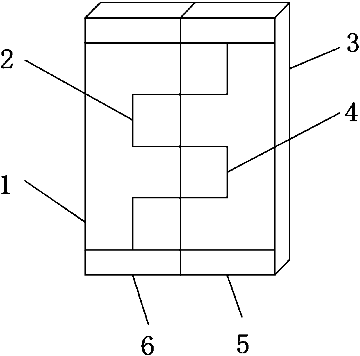
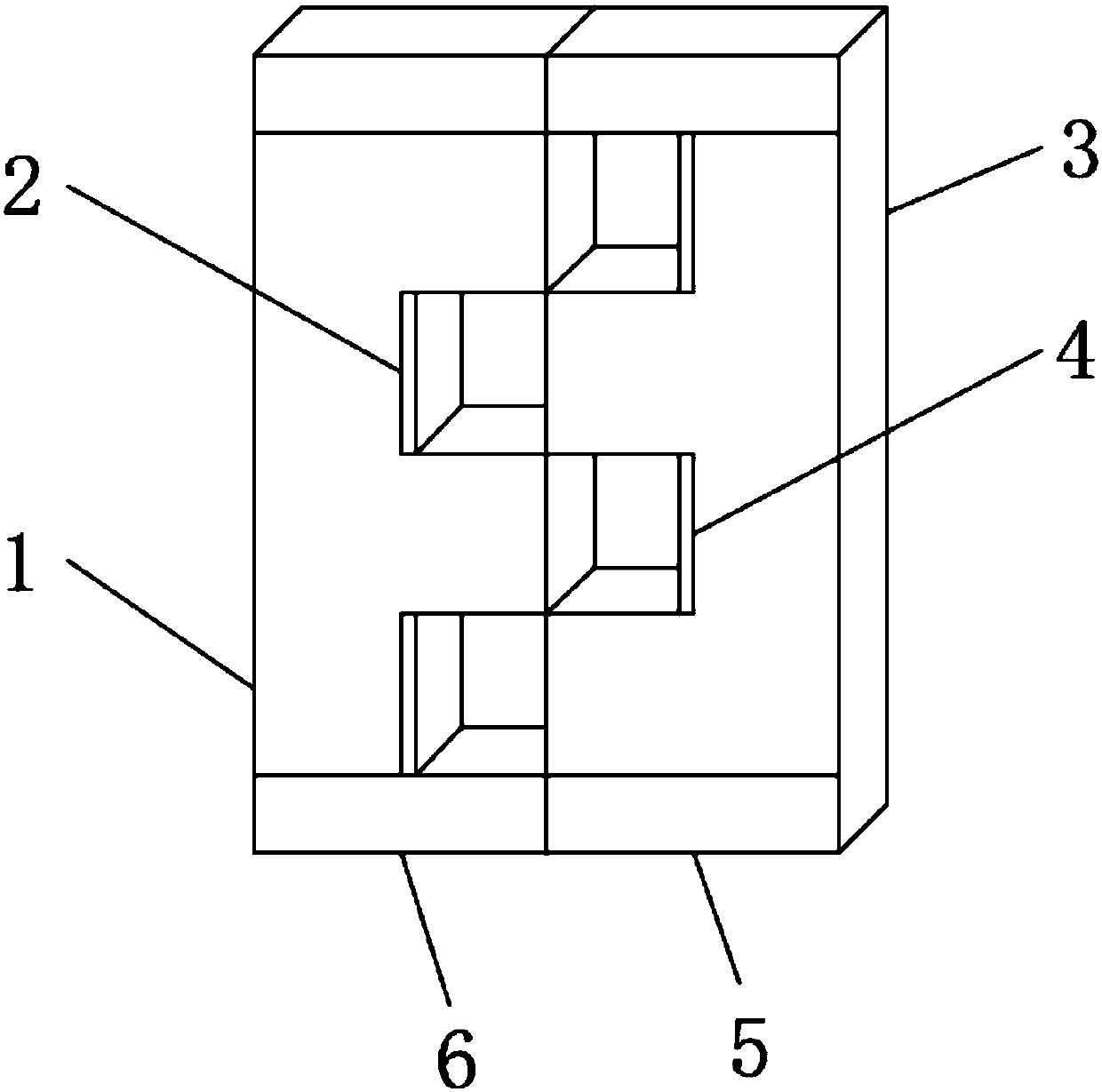
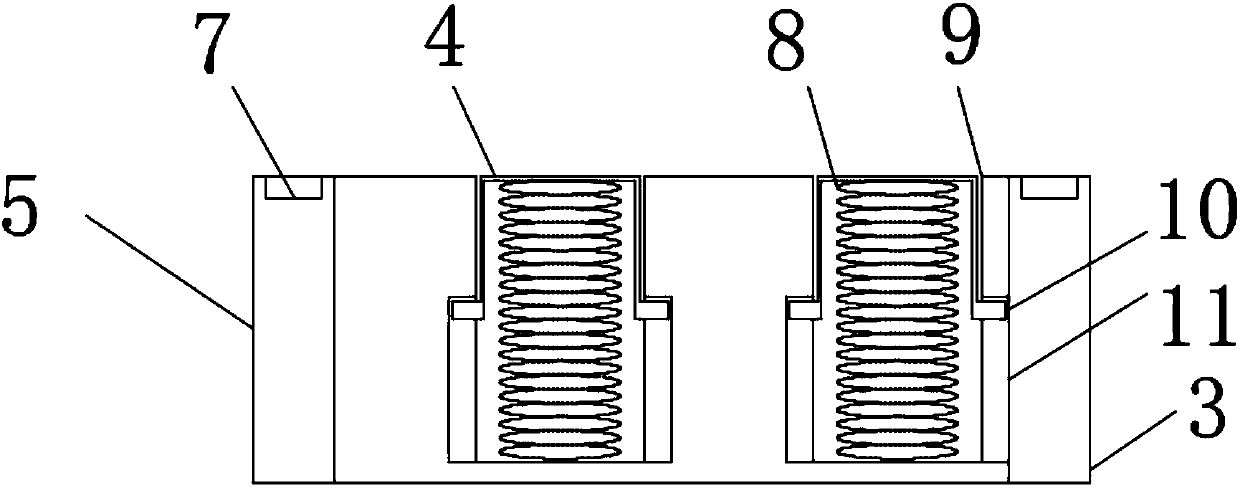
[0022] see Figure 1-Figure 6 , the present invention provides a technical solution: a magnetic switch door protection and safety relay device, including a first magnetic door panel 1, a first limit plate 6 is welded below the first magnetic door panel 1, and a There is a first retractable protective plate 2, a second magnetic door plate 3 is arranged on one side of the first magnetic door plate 1, a second limit plate 5 is welded under the second magnetic doo...


PUM


Abstract

The invention discloses a protection and safety relay device of a magnetically opened and closed door. The relay device comprises a first magnetic door sheet, a first limiting plate is welded below the first magnetic door sheet, a first extendable protective plate is arranged on the first magnetic door sheet, a second magnetic door sheet is arranged on one side of the first magnetic door sheet, asecond limiting plate is welded below the second magnetic door sheet, and a magnetic switch is inlaid in one end of the second limiting plate; the first extendable protective plate and a second extendable protective plate are arranged on the magnetic opening and closing door, so that when users carelessly insert limbs of the users into a monitoring blind area of the magnetically opened and closeddoor, and the first extendable protective plate or the second extendable protective plate which is in contact with the limbs of the users can be retracted; the magnetic switch is arranged on the magnetically opened and closed door and can provide electrical protection for the users; and sound insulation cotton is arranged on the magnetically opened and closed door so that the mute effect can be better when the magnetically opened and closed door is used.

Description

technical field [0001] The invention belongs to the technical field of magnetic switches, in particular to a magnetic switch door protection and safety relay device. Background technique [0002] A magnetic switch is a line switching device controlled by a magnetic field signal, also called a magnetic switch. Commonly used magnetic switches have two types: single contact and double contact. [0003] However, due to the relatively simple structure of the traditional magnetic switch door, there is a monitoring blind area in the use of the magnetic switch door. If the user's limbs accidentally enter the monitoring blind area of ​​the magnetic switch door, the user is easily caught by the magnetic switch door, which is harmful to the user's body. Health hazards. Therefore, the use of traditional magnetic switch doors has potential safety hazards. Secondly, due to the lack of corresponding sound insulation structures of traditional magnetic switch doors, the sound insulation effe...

Claims


Application Information

Patent Timeline
IPC IPC(8): B66B13/14B66B13/26
CPCB66B13/143B66B13/26
Inventor 周华
Owner WUXI UNITE ENERGY TECH CO LTD
Learn More