Construction Method of Cast-in-place Pile Using Rotating and Stretching Reinforcement Cage

A construction method and reinforcement cage technology, which are applied in sheet pile walls, infrastructure engineering, construction, etc., can solve the problems that the pile length cannot be increased arbitrarily, affect the bearing performance of the pile, and increase the engineering cost, so as to reduce the cost of piling construction. , The effect of increasing the bearing load and increasing the force performance of the side wall

Active Publication Date: 2019-07-23
武汉志和岩土工程有限公司
View PDF1 Cites 0 Cited by
  • Summary
  • Abstract
  • Description
  • Claims
  • Application Information

AI Technical Summary

Problems solved by technology

However, the pile length cannot be increased arbitrarily, because not only the project cost is greatly increased, but also the pile length is limited by the slenderness ratio in the relevant design specifications
For example, CN104179174A discloses a kind of porous grouting pipe special-shaped pile. Grouting holes are set on the side wall of the pipe pile, and the concrete overflows from the grouting hole to form a stone body to improve the friction coefficient of the side wall, thereby increasing the frictional resistance. However, the The stone body does not contain steel bars, the stone body is relatively brittle, and is prone to fracture under high-strength pressure, thus affecting the load-bearing performance of the pile

Method used


Image

  • Construction Method of Cast-in-place Pile Using Rotating and Stretching Reinforcement Cage
  • Construction Method of Cast-in-place Pile Using Rotating and Stretching Reinforcement Cage
  • Construction Method of Cast-in-place Pile Using Rotating and Stretching Reinforcement Cage

Examples


Embodiment 1

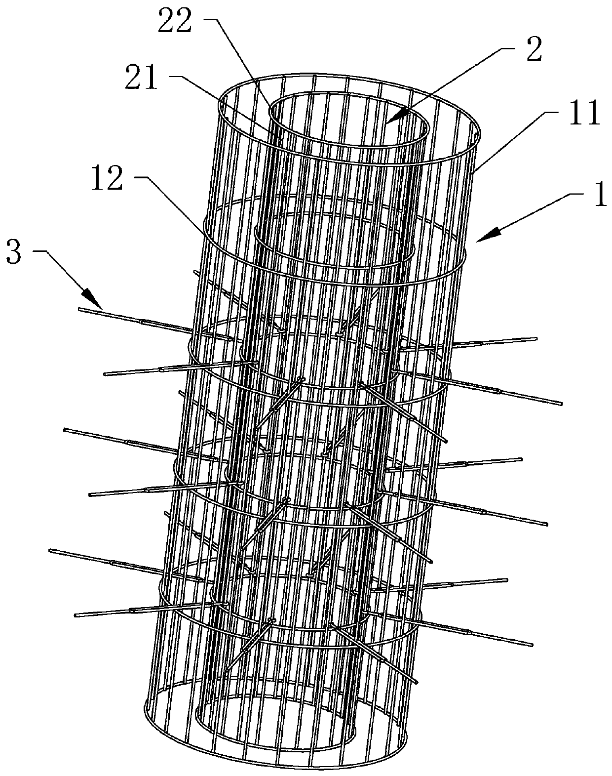
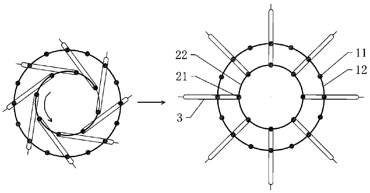
[0036] according to figure 1 , figure 2 , image 3 As shown, the construction method of cast-in-situ piles made of rotating and stretching steel cages includes the following steps:

[0037] Step 1, prepare the reinforcement cage: design and calculate the size of the reinforcement cage, and make the reinforcement cage according to the size;

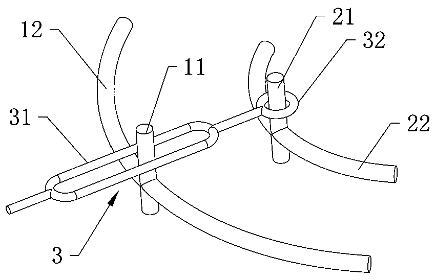
[0038] The reinforcement cage includes an outer cage body 1, an inner cage body 2 and stretching ribs 3, the inner cage body 2 is set in the outer cage body 1, the outer cage body 1 includes the outer cage main reinforcement 11 and the outer cage hoop 12, and the inner cage body 2 includes The inner cage main rib 21 and the inner cage stirrup 22, the top of the stretch rib 3 protrudes outside the outer cage body 1, the root is hinged on the inner cage body 2, and the middle part is provided with a connecting area 31, and the stretching rib 3 passes through the connecting area 31 and the outer cage body 1 Connected, the stretch rib 3 mo...

Embodiment 2

[0047] The difference from the above-mentioned embodiment 1 is that, according to Figure 4 As shown, the root of the extension rib 3 is provided with a hinged ring 32, the hinged ring 32 is sleeved on the main rib 21 of the inner cage, the connecting area 31 and the hinged ring 32 are connected into one body, and the closed ring of the connecting area 31 overlaps with the steel bars of the hinged ring 32 .

Embodiment 3

[0049] The difference from the above-mentioned embodiment 1 is that, according to Figure 5 As shown, the root of the stretching rib 3 is provided with a hinged ring 32, the hinged ring 32 is sleeved on the main rib 21 of the inner cage, and the connecting area 31 is composed of two cross-shaped elongated rings, and the two elongated rings connect the connecting area. 31 is divided into two intersecting first communication areas and second communication areas, the outer cage main reinforcement 11 runs through the first communication area, and the outer cage stirrup 12 runs through the second communication area.


PUM


Abstract

The invention relates to the field of construction, in particular to a construction method of adopting a rotary extension type steel reinforcement cage to manufacture a cast-in-place pile. The construction method comprises the following steps that 1, the steel reinforcement cage is prepared, specifically, the size of the steel reinforcement cage is designed and calculated, the steel reinforcementcage is manufactured according to the size, and after the steel reinforcement cage is prepared, the positions of extension ribs are required to be marked on the top of the steel reinforcement cage; 2,a pile hole is punched, specifically, a certain gap is reserved between the inner diameter of the pile hole and the outer diameter of the steel reinforcement cage; 3, side holes are formed, specifically, the multiple side holes are formed in the side wall of the pile hole by using counterboring equipment, the positions of the side holes are marked on the top of the pile hole, and the elevation ofthe side holes is set; 4, the steel reinforcement cage is hoisted and put down, specifically, the steel reinforcement cage is hoisted to the position above the pile hole, and the position of the steel reinforcement cage is adjusted through rotating in the hoisting process, so that the marks, on the top of the steel reinforcement cage, of the extension ribs are aligned with the marks, on the top of the pile hole, of the side holes, the steel reinforcement cage is put down and is hoisted and put to the designated height corresponding to the elevation of the side holes, an inner cage body is rotated, and thus the top ends of the extension ribs gradually extend to the outer side of an outer cage body; and 5, concrete is poured to form the pile.

Description

technical field [0001] The invention relates to the construction field, in particular to a construction method for making cast-in-place piles by adopting a rotating and stretching steel cage. Background technique [0002] Pile structures are commonly used foundation structures in buildings such as houses, roads, bridges and docks. Among them, the friction pile is a pile that relies on the friction resistance of the pile side to support the vertical load. From the point of view of the principle of the friction pile, the friction resistance of the pile side is not only related to the nature of the soil, construction technology, pile material, etc., but also related to the periphery of the pile section. The perimeter and the concave-convex shape of the pile side surface are directly related. However, the cross-sectional shape of the conventional reinforced concrete pile is constant along the longitudinal direction, and the cross-sectional shape is also simple square or circula...

Claims


Application Information

Patent Timeline
Patent Type & Authority Patents(China)
IPC IPC(8): E02D5/34
CPCE02D5/34
Inventor 胡勇李鹏胡涛李波
Owner 武汉志和岩土工程有限公司
Why Eureka
Try Eureka