Spindle lock-up energy storage mechanism for sharing fitness equipment

A technology of fitness equipment and energy storage mechanism, which is applied in the direction of mechanical power generation mechanism, machine/engine, mechanical power generation by physical force, etc., and can solve the problems of restricting the time and place of exercise

Inactive Publication Date: 2018-04-17
张凯
View PDF0 Cites 0 Cited by
  • Summary
  • Abstract
  • Description
  • Claims
  • Application Information

AI Technical Summary

Problems solved by technology

[0002] At present, outdoor fitness equipment is simple, and users can only do some simple fitness and physical activity; for young people, they generally need to do exercises for all parts of their body, so they need to go indoors to do some professional fitness equipment However, these fitness equipment are often affected by fitness clubs, and you must go to a special place to do exercise, which greatly limits the time and place of exercise; because the existing shared bicycles are very simple to use and can be used at any time, So there is the idea of ​​designing shared fitness equipment, so it is necessary to design a shaft locking energy storage mechanism for shared fitness equipment

Method used


Image

  • Spindle lock-up energy storage mechanism for sharing fitness equipment
  • Spindle lock-up energy storage mechanism for sharing fitness equipment
  • Spindle lock-up energy storage mechanism for sharing fitness equipment

Examples


Embodiment Construction

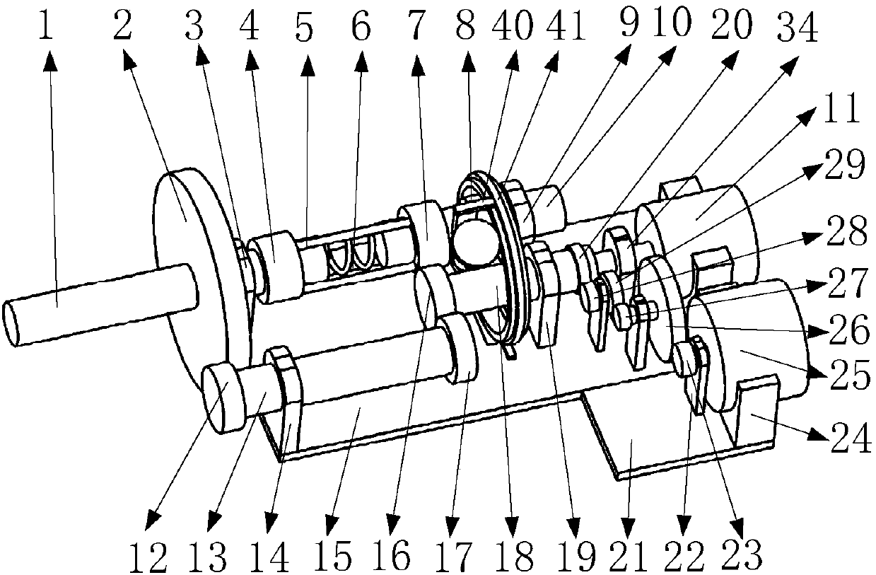
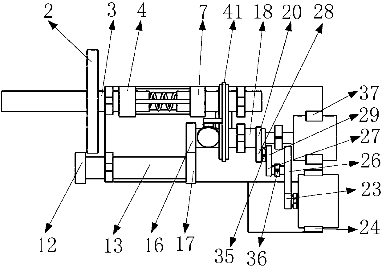
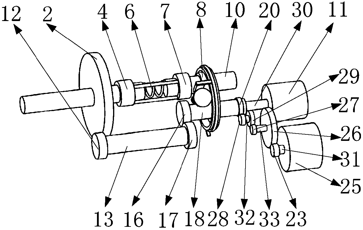
[0022] Such as figure 1 , 2 As shown, it includes input shaft 1, large gear 2, input shaft support 3, threaded ring 4, ring support 5, torsion spring 6, fixed ring 7, locking gear 8, output shaft support 9, output shaft 10, motor 11 , pinion 12, transition shaft 13, transition shaft support 14, first fixed plate 15, first worm gear 16, transition gear 17, worm 18, worm support 19, power generation gear 20, second fixed plate 21, generator shaft Support 22, generator gear 23, generator support 24, generator 25, first amplifying gear 26, second amplifying gear 27, third magnetic control gear 28, fourth amplifying gear 29, motor shaft 30, generator shaft 31 , the first shaft 32, the second shaft 33, the motor shaft support 34, the first enlarged support 35, the second enlarged support 36, the motor support 37, the battery 38, the first support plate 40, the ring gear ring 41, and the ring gear ring is fixed Block 42, ring gear 43, second support 44 plates, transition shaft 45, ...


PUM


Abstract

The invention belongs to the technical field of rotating shaft locking, and in particular relates to a rotating shaft locking energy storage mechanism used by shared fitness equipment. In the present invention, a ring gear hole is opened on the first fixing plate to facilitate the installation of the ring gear ring; the input shaft supports and The function of the transition shaft support symmetrically installed on the same side of the first fixed plate is that the input shaft support facilitates the installation of the input shaft, and the transition shaft support facilitates the installation of the transition shaft support; the output shaft support and the worm support are installed on the first fixed plate The function of the upper end surface is to facilitate the installation of the output shaft and the worm; the role of the motor shaft support installed on the end surface of the first fixed plate is to facilitate the support of the motor shaft; one end of the worm is installed on the end surface of the motor shaft, and the other end of the worm passes through the worm support The function is to transmit the motion on the motor rotating shaft to the first worm gear, and the rotating shaft locking technology in the present invention has the functions of locking and protecting shared fitness equipment.

Description

technical field [0001] The invention belongs to the technical field of rotating shaft locking, and in particular relates to a rotating shaft locking energy storage mechanism used by shared fitness equipment. Background technique [0002] At present, outdoor fitness equipment is simple, and users can only do some simple fitness and physical activity; for young people, they generally need to do exercises for all parts of their body, so they need to go indoors to do some professional fitness equipment However, these fitness equipment are often affected by fitness clubs, and you must go to a special place to do exercise, which greatly limits the time and place of exercise; because the existing shared bicycles are very simple to use and can be used at any time, So just have the idea of ​​designing shared fitness equipment, so just need to design a kind of rotating shaft locking energy storage mechanism that shared fitness equipment uses. [0003] The present invention designs a ...

Claims


Application Information

Patent Timeline
Patent Type & Authority Applications(China)
IPC IPC(8): F03G5/00F16H63/34
CPCF03G5/00F16H63/34
Inventor 张凯
Owner 张凯
Why Eureka
Try Eureka