
Two-channel stainless steel plunger valve element

A stainless steel column and plunger valve technology, which is applied in the valve field of food and beverage filling technology

Inactive Publication Date: 2018-04-17
成都市同展食品有限公司
View PDF0 Cites 2 Cited by
  • Summary
  • Abstract
  • Description
  • Claims
  • Application Information

AI Technical Summary

Problems solved by technology

[0008] The spools of the existing four-way valves can only be connected in twos and cut off in twos, but cannot realize the mutual conversion of the flow directions of the four channels to achieve simultaneous connection and simultaneous closure.

Method used


Image

  • Two-channel stainless steel plunger valve element
  • Two-channel stainless steel plunger valve element
  • Two-channel stainless steel plunger valve element

Examples


Embodiment

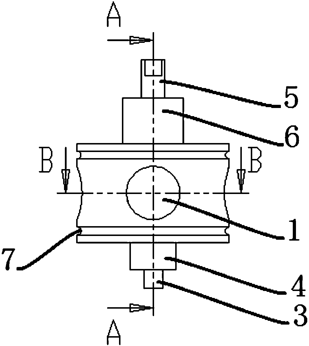
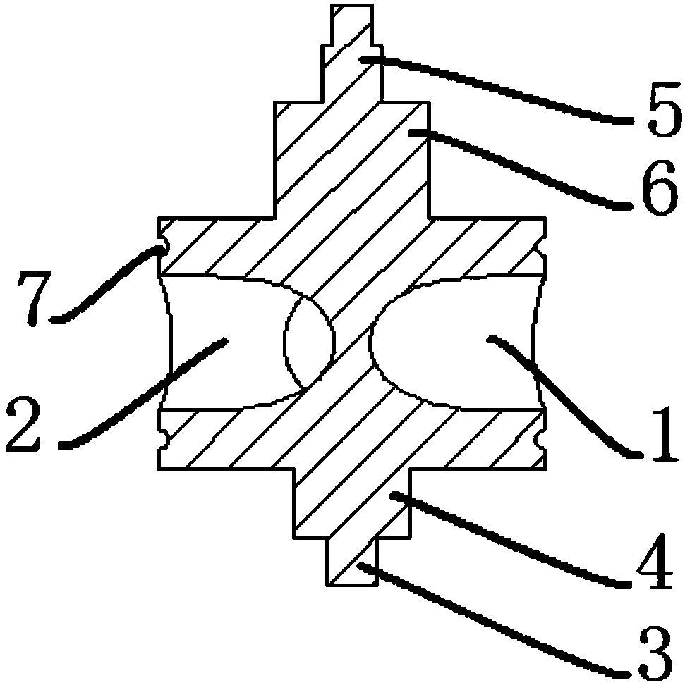
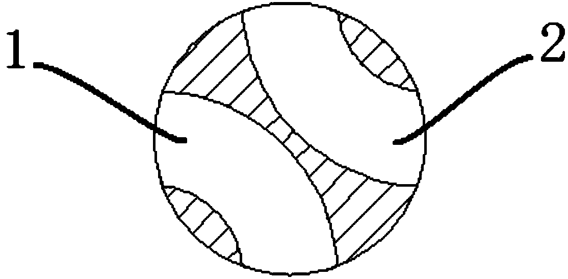
[0026] like Figure 1 to Figure 3 As shown, the present invention has a double-channel stainless steel plunger valve core, the plunger valve core is a cylindrical structure, and the radial direction of the plunger valve core is provided with a first U-shaped channel 1, a second U-shaped channel 2, and a first U-shaped channel 2. U-shaped channel 1 and the second U-shaped channel 2 are not connected. The first U-shaped channel 1 and the second U-shaped channel 2 of the plunger spool are symmetrical left and right along the center line of the plunger spool, and the channel openings of the first U-shaped channel 1 and the second U-shaped channel 2 are along the center line of the plunger spool. uniformly distributed around the circumference.

[0027] In a preferred embodiment, one end of the plunger spool is provided with a bearing rod 3, and the other end of the plunger spool is provided with a rotating shaft 5, the bearing rod 3 and the rotating shaft 5 are integrally formed w...


PUM


Abstract

The invention discloses a double-channel stainless steel plunger valve core. The plunger valve core is a cylindrical structure. The plunger valve core is provided with a first U-shaped channel and a second U-shaped channel in the radial direction. The first U-shaped channel and the The second U-shaped channel is not connected. The first U-shaped channel of the plunger spool, the second U-shaped channel is symmetrical to the left and right along the center line of the plunger spool, and the channel openings of the first U-shaped channel and the second U-shaped channel are evenly distributed along the circumference of the plunger spool arrangement. In the present invention, two symmetrical U-shaped passages are arranged on the plunger valve core. When the plunger valve core is installed on the four-channel valve body, the outlets of the U-shaped passages communicate with the four channels of the four-channel valve body respectively. When changing the plunger spool, it only needs to turn the direction handwheel 90 degrees to change the connection direction of the four channels, realizing the multi-purpose pipeline connection mode.

Description

technical field [0001] The invention relates to the technical field of valves for food and beverage filling technology, in particular to a double-channel stainless steel plunger valve core. Background technique [0002] Valves are pipeline accessories used to open and close pipelines, control flow direction, adjust and control the parameters (temperature, pressure and flow) of the conveying medium. According to its function, it can be divided into shut-off valve, check valve, regulating valve and so on. [0003] The valve is a control component in the fluid delivery system, which has functions such as cut-off, adjustment, flow diversion, reverse flow prevention, pressure stabilization, flow diversion or overflow pressure relief. Valves used in fluid control systems range from the simplest cut-off valves to various valves used in extremely complex automatic control systems, with a wide variety of varieties and specifications. [0004] In terms of technical support for valve...

Claims


Application Information

Patent Timeline
Patent Type & Authority Applications(China)
IPC IPC(8): F16K5/04F16K11/085
CPCF16K5/0407F16K11/085
Inventor 李敏
Owner 成都市同展食品有限公司
Learn More