
Concrete crack resistance detection machine for building civil engineering

A concrete and detection machine technology, applied in the direction of applying stable tension/pressure to test the strength of materials, measuring devices, strength characteristics, etc., can solve the problem of affecting the integrity, durability, even safety and stability of buildings, prone to cracks, detection The data is not accurate and comprehensive enough to achieve the effect of convenient scenario simulation, changing the properties of concrete, and comprehensive testing results

Inactive Publication Date: 2022-03-08
吴东海
View PDF0 Cites 0 Cited by
  • Summary
  • Abstract
  • Description
  • Claims
  • Application Information

AI Technical Summary

Problems solved by technology

[0002] The crack resistance of concrete refers to the ability of concrete to resist cracking. The crack resistance of concrete is a comprehensive performance, which is related to tensile strength, ultimate tensile deformation capacity, tensile elastic modulus, autogenous volume deformation, creep and thermal properties. There is a certain relationship, because the tensile strength of concrete is much smaller than the compressive strength, the ultimate tensile deformation is very small, under the action of external force, temperature change, humidity change, etc., cracks are prone to occur, and cracks in concrete and reinforced concrete will affect the quality of buildings. Integrity, durability, and even safety and stability are usually not dedicated to simulating the test results of concrete in different situations, and the test data is not accurate and comprehensive enough

Method used


Image

  • Concrete crack resistance detection machine for building civil engineering
  • Concrete crack resistance detection machine for building civil engineering
  • Concrete crack resistance detection machine for building civil engineering

Examples


Embodiment Construction

[0018] In order to make the purpose and advantages of the present invention clearer, the present invention will be described in detail below in conjunction with the examples, and it should be understood that the following words are only used to describe a kind of concrete crack resistance detector or several specific concrete crack resistance detectors for civil engineering of the present invention. Embodiments do not strictly limit the protection scope of the specific claims of the present invention. As used herein, the terms up, down and left and right are not limited to their strict geometric definitions, but include reasonable and inconsistent tolerances for machining or human errors. The specific characteristics of this kind of concrete crack resistance testing machine for civil engineering are described in detail below:

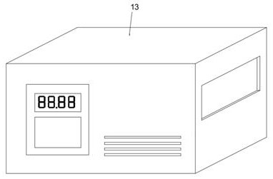
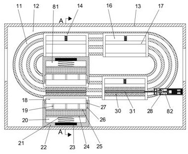
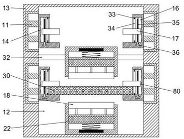
[0019] Refer to attached Figure 1-Figure 5 , according to an embodiment of the present invention, a concrete crack resistance tester for construction ...


PUM


Abstract

The invention discloses a building civil concrete crack resistance detection machine which comprises a shell, a working cavity is formed in the shell, concentric-square-shaped electric sliding rails with symmetrical positions are fixedly arranged on the front wall and the rear wall of the working cavity, and the end faces, close to the symmetrical center, of the concentric-square-shaped electric sliding rails are slidably connected with L-shaped mounting blocks with evenly distributed positions; the concrete crack resistance detection device is provided with a strip-shaped mounting block, a pressurizing block and a clamping block, the crack resistance of a concrete block can be detected when the concrete block is pressurized and loaded, water with oxygen can be injected into a hollow steel bar in concrete through the strip-shaped mounting block, so that the property of the concrete is changed for detection, and the concrete crack resistance detection device has the advantages of being accurate in detection result and multiple in simulation scene; a cam, an exhaust pipeline and a drainage pipeline are further arranged, connection and communication of the pipeline and the hollow steel bar can be achieved, water is injected into the steel bar, air is exhausted, the purpose of changing the concrete property is achieved, and the device has the advantages of being comprehensive in detection result and convenient and fast in scene simulation.

Description

technical field [0001] The invention relates to the technical field of concrete crack resistance, in particular to a concrete crack resistance detector for civil engineering. Background technique [0002] The crack resistance of concrete refers to the ability of concrete to resist cracking. The crack resistance of concrete is a comprehensive performance, which is related to tensile strength, ultimate tensile deformation capacity, tensile elastic modulus, autogenous volume deformation, creep and thermal properties. There is a certain relationship, because the tensile strength of concrete is much smaller than the compressive strength, the ultimate tensile deformation is very small, under the action of external force, temperature change, humidity change, etc., cracks are prone to occur, and cracks in concrete and reinforced concrete will affect the quality of buildings. Integrity, durability, and even safety and stability are usually not dedicated to simulating the test results...

Claims


Application Information

Patent Timeline
Patent Type & Authority Applications(China)
IPC IPC(8): G01N3/02G01N3/04G01N3/12
CPCG01N3/02G01N3/04G01N3/12G01N2203/0003G01N2203/0019G01N2203/0048G01N2203/0062G01N2203/0236
Inventor 吴东海
Owner 吴东海
Learn More