Domestic appliance having a cleaning apparatus for heat exchangers

A technology for heat exchangers and household appliances, applied to washing devices, household clothes dryers, applications, etc., can solve the problems of reducing the efficiency of the first heat exchanger 4, and achieve the effect of increasing the effective distance

Active Publication Date: 2018-04-17
BSH BOSCH & SIEMENS HAUSGERAETE GMBH
View PDF7 Cites 3 Cited by
  • Summary
  • Abstract
  • Description
  • Claims
  • Application Information

AI Technical Summary

Problems solved by technology

However, the moisture film also retains particles present in the process air P, such as fluff and hair, on the heat exchanger surfaces, which also remain stuck there after evaporation of the moisture film and can degrade the first heat exchanger 4 s efficiency

Method used


Image

  • Domestic appliance having a cleaning apparatus for heat exchangers
  • Domestic appliance having a cleaning apparatus for heat exchangers
  • Domestic appliance having a cleaning apparatus for heat exchangers

Examples


Embodiment Construction

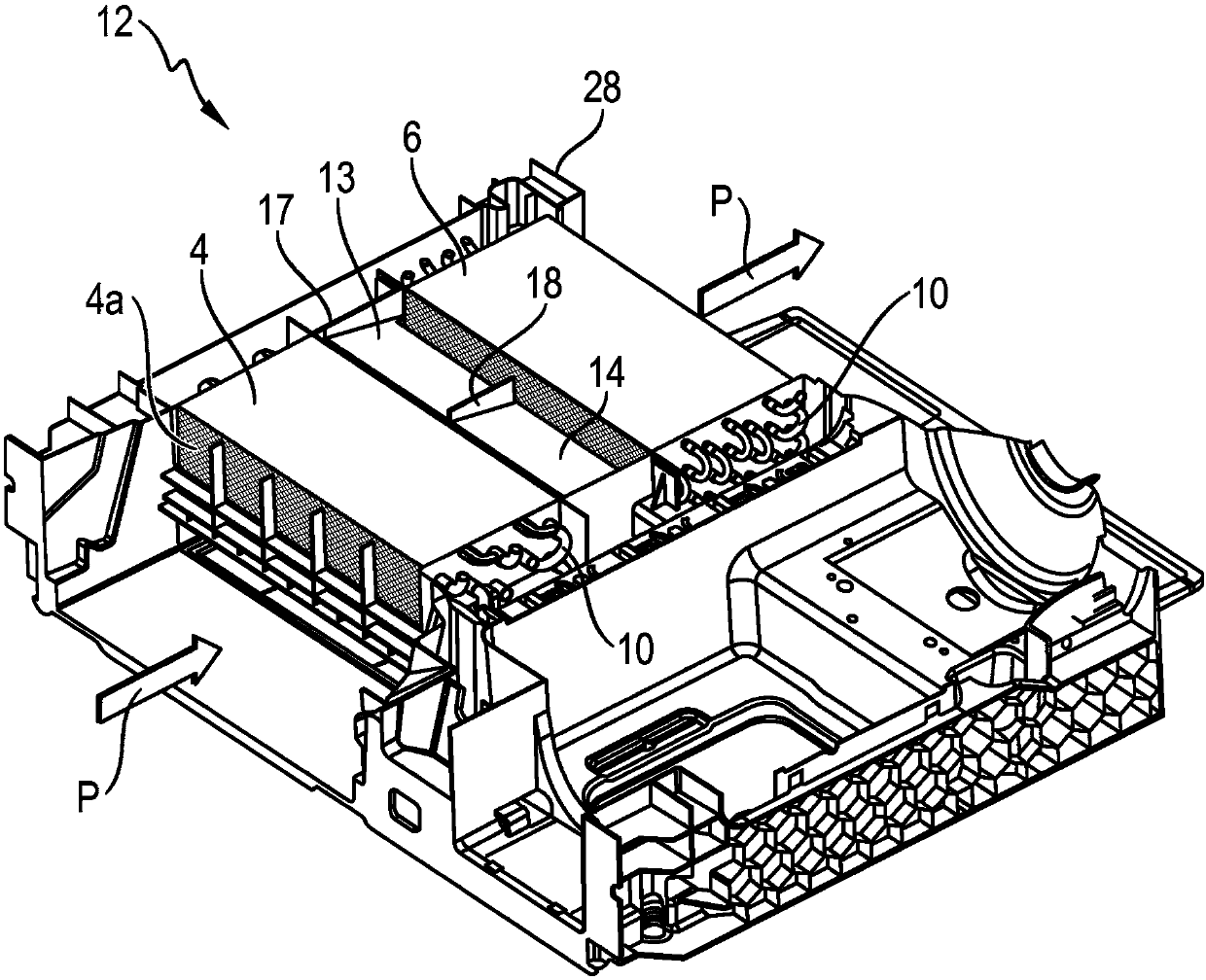
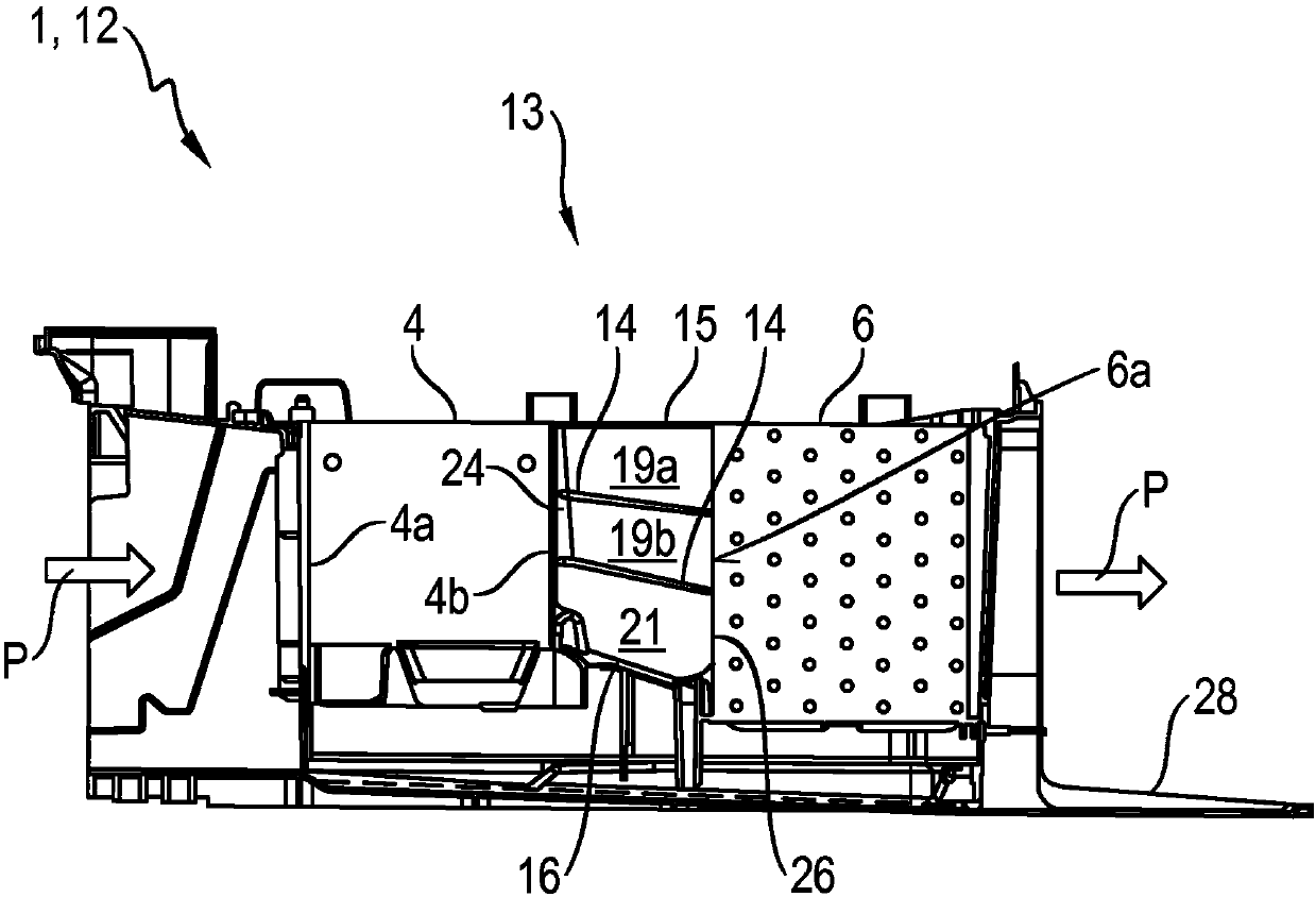
[0053] figure 2 Shown obliquely from above is a partial view of a base unit 12 of a heat pump dryer 1 , which has a first heat exchanger 4 and which is arranged at a distance in the flow direction of the process air P on said base unit 12 . The second heat exchanger 6 behind the first heat exchanger. In this case, a flow-guiding structure 13 is additionally arranged between the two heat exchangers. The associated sectional plane lies in the horizontal plane such that the top cover of the air guiding structure 13 is cut away and is therefore not shown. That is to say, the upper side of the air guiding structure 13 is shown open.

[0054] The first heat exchanger 4 has a square basic shape. Moist process air P enters at its air inlet face 4 a and is cooled and completely condensed there. The process air P then flows through the flow-guiding structure 13 and through the second heat exchanger 6 , where it is heated. The second heat exchanger 6 likewise has a square basic sha...


PUM


Abstract

The invention relates to a domestic appliance 1 having a first heat exchanger 4 and a second heat exchanger 6, which are arranged one behind the other at a distance from each other in an air flow channel 3 with respect to the flow direction of said air flow channel, and a cleaning apparatus 5 for cleaning the first heat exchanger 4 by means of cleaning liquid W, wherein a flow-guiding structure 13is present in the air flow channel 3 between the first heat exchanger 4 and the second heat exchanger 6, which flow-guiding structure has at least one planar flow-guiding element 14, which is oriented at least approximately horizontally between the first heat exchanger 4 and the second heat exchanger 6, wherein the at least one flow-guiding element 14 is arranged above a bottom 16 of the flow-guiding structure 13. The invention can be applied particularly advantageously to clothes-drying appliances, in particular recirculating-air clothes-drying appliances. The invention can be applied particularly advantageously to domestic appliances having a heat pump.

Description

technical field [0001] The invention relates to a domestic appliance having a first heat exchanger and a second heat exchanger and a cleaning device for cleaning the first heat exchanger with a cleaning liquid, the first heat exchanger and the second heat exchanger In the air flow channel, they are arranged one behind the other at a distance with reference to their flow direction. The invention can be used particularly advantageously in laundry drying appliances, in particular in circulating air laundry drying appliances. The invention can be used particularly advantageously in domestic appliances with heat pumps. Background technique [0002] figure 1 A simplified diagram of a heat pump clothes dryer 1 of a corresponding type is shown. The heat pump dryer has a receiving chamber for the laundry to be dried (not shown), here for example a horizontally rotatable washing drum 2 . During the drying process, hot and dry process air P enters the washing drum 2 from the proces...

Claims


Application Information

Patent Timeline
IPC IPC(8): D06F58/22D06F58/24D06F58/20
CPCD06F58/20D06F58/206D06F58/22D06F58/24
Inventor R·伯梅尔斯M·马尼希M·舒伯特
Owner BSH BOSCH & SIEMENS HAUSGERAETE GMBH
Why Eureka
Try Eureka