
A tool for welding assembly of head and flange

A flange welding and head technology, which is applied in welding equipment, auxiliary welding equipment, welding/cutting auxiliary equipment, etc., can solve the problems that the welding and assembly quality of the head and flange cannot be satisfied.

Active Publication Date: 2019-09-17
XIAN AEROSPACEMOTOR MACHINE FACTORY
View PDF6 Cites 0 Cited by
  • Summary
  • Abstract
  • Description
  • Claims
  • Application Information

AI Technical Summary

Problems solved by technology

[0003] In order to overcome the deficiency in the prior art that cannot meet the welding and assembly quality of the head and the flange, the present invention proposes a tooling for the welding and assembling of the head and the flange

Method used


Image

  • A tool for welding assembly of head and flange
  • A tool for welding assembly of head and flange
  • A tool for welding assembly of head and flange

Examples


Embodiment Construction

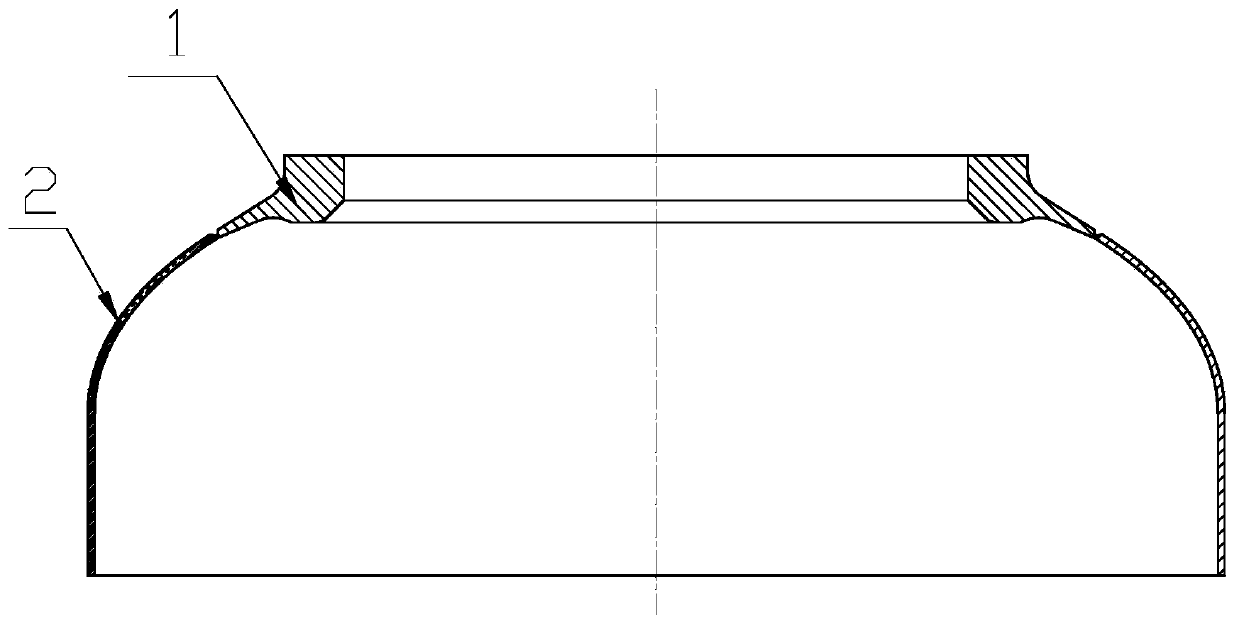
[0019] The invention designs and manufactures welding and assembly tooling of different specifications for different sizes of heads and flanges.

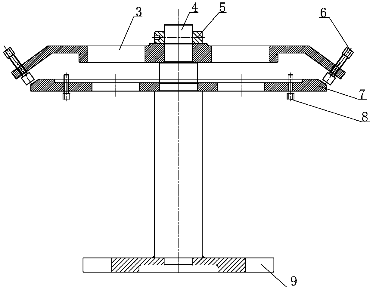
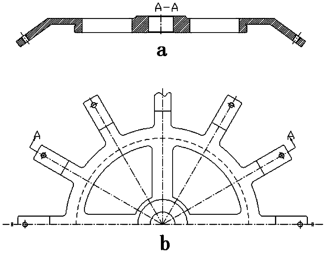
[0020] This embodiment is a head and flange welding assembly tool, including a pressure plate 3, a main shaft 4, a compression nut 5, a misalignment adjustment bolt 6, a backing plate 7, a lift adjustment bolt 8 and a bottom plate 9. The pressure plate 3 and the backing plate 7 are set on the upper part of the main shaft, and are fastened by the compression nut 5 ; the pressure plate 3 is located above the backing plate 7 . The ends of each mounting rod located on the circumference of the pressure plate are respectively equipped with a misalignment adjustment bolt 6, and the tops on each misalignment adjustment bolt correspond to the head supporting surface on the edge of the upper surface of the backing plate 7 circumference. The lower end of the main shaft 4 is fixed on the center of the bottom plate 9 . Lifting amount adjusting ...


PUM


Abstract

The invention provides a tool for welding assembly of an end socket and a flange. The upper portion of a main shaft is sleeved with a pressing plate and a cushion plate, and the pressing plate is madeto be located above the cushion plate. The end of each mounting rod on the circumference of the pressing plate is provided with an alignment tolerance adjusting bolt, and push heads on the alignmenttolerance adjusting bolts correspond to the end socket supporting faces of the edge of the upper surface of the cushion plate. Raised height adjusting bolts are mounted on the cushion plate. A plurality of radially-extending supporting rods are arranged on the surface of the outer circumference of the cushion plate, and the edge of the upper surface of each supporting rod is an arc face matched with the surface of an inner arc of the end socket. Mounting holes for the raised height adjusting bolts are formed in the supporting rods correspondingly. According to the tool for welding assembly ofthe end socket and the flange, before-welding assembly of ellipsoidal holed end sockets of various thicknesses and diameters and the flange can be achieved, and the assembly quality meets the weldingtechnological requirement. The size phi of an inner hole of the related flange is 100-1000 mm, the diameter phi of the end socket is 300-2000 mm, and the assembly sizes of the all types of flanges andend sockets can meet the welding technological requirement.

Description

technical field [0001] The invention relates to the field of assembly technology. Specifically, a welding assembly tool for the opening of the ellipsoidal head and the flange was designed and manufactured. Background technique [0002] The ellipsoidal heads at both ends of the metal shell of a solid rocket motor have openings, and flanges need to be welded at the openings for connection with other structures. Due to the high standard requirements of the solid rocket motor on the shape accuracy, the flatness of the end face of the flange must be within a certain range after the welding of the head and the flange is completed. In addition, during the welding process of the flange and the open-hole head, due to the weight of the flange itself and the melting of the contact parts during welding, it is easy to cause the flange to collapse and the internal profile of the head does not meet the design requirements. Therefore, when the head and flange are welded, there are high re...

Claims


Application Information

Patent Timeline
Patent Type & Authority Patents(China)
IPC IPC(8): B23K37/053
Inventor 刘丽莉杨军魁国祯胡春海秦占玲王秉祥熊然张珊李海荣陈林
Owner XIAN AEROSPACEMOTOR MACHINE FACTORY
Learn More