Power-on test device for an integrated lamp strip

A power-on test and integrated technology, applied in the direction of measuring devices, instruments, etc., can solve the problem of insufficient test points, etc., and achieve the effect of accurate test results and easy detection

Inactive Publication Date: 2018-04-20
四川施克电器有限公司
View PDF0 Cites 1 Cited by
  • Summary
  • Abstract
  • Description
  • Claims
  • Application Information

AI Technical Summary

Problems solved by technology

[0006] The technical problem to be solved by the present invention is the detection method of the traditional patch LED light, which is to conduct a power-on test on the LED light bar, and detect the LED lights with unstable brightness on the light bar for rework, but the point of the test method Insufficient, there will be many missing problems, the purpose is to provide power-on test equipment suitable for integrated light bars to solve the above problems

Method used


Image

  • Power-on test device for an integrated lamp strip
  • Power-on test device for an integrated lamp strip
  • Power-on test device for an integrated lamp strip

Examples


Embodiment 1

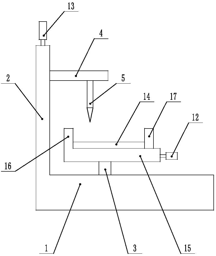
[0024] Such as figure 1 As shown, the electrification test equipment suitable for integrated light strips includes a base 1, a support plate 2 is fixedly arranged on the base 1, a rotating shaft 3 is arranged on the base 1, and a placing plate 15 is arranged on the rotating shaft 3, and the placing plate 15 can The rotating shaft 3 rotates around its axial direction together, and one end of the placing disc 15 is provided with a fixed baffle 16, and the other end is provided with a movable baffle 17, and the movable baffle 17 can move along the surface of the placing disc 15 or be fixed on the placing disc 15; The support plate 2 is provided with a movable mounting plate 4, and the movable mounting plate 4 can move along the support plate 2 or be fixed on the support plate 2; the movable mounting plate 4 is provided with a height detection head 5; the movable mounting plate 4 is provided with a groove, the height detection head 5 is provided with a protrusion, the groove is fi...

Embodiment 2

[0027] This embodiment is based on Embodiment 1 to further illustrate the present invention.

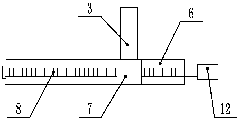
[0028] Such as figure 2 As shown, it is suitable for the electrification test equipment of the integrated light bar. The placement plate 15 is provided with a guide groove-6, and the guide groove-6 is provided with a sliding block-7, and the sliding block-7 is screwed with a screw rod-8. , one end of the screw one 8 is connected with the guide groove one 6, and the other end is located outside the placement plate 15, the screw one 8 can rotate around its own axis direction, so that the sliding block one 7 can move along the axis direction of the screw one 8, and the movable stop The plate 17 is fixed on the sliding block 17, and the position of the sliding block 17 and the movable baffle 17 can be adjusted by turning the screw rod 17, so that it is suitable for patch LED light strips 14 of different specifications and sizes, and the screw rod 18 is located at the One end outside th...

Embodiment 3

[0030] This embodiment is based on Embodiment 1 to further illustrate the present invention.

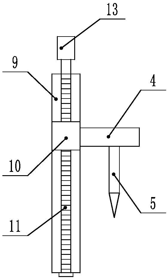
[0031] Such as image 3As shown, it is suitable for the electrification test equipment of the integrated light bar. The support plate 2 is provided with a guide groove 2 9, and the guide groove 2 9 is provided with a sliding block 2 10, and the sliding block 10 is screwed with a screw rod 2 11. One end of the screw 11 is connected to the guide groove 9, and the other end is located outside the support plate 2. The screw 11 can rotate around its own axis to make the sliding block 10 move along the axis of the screw 11. The movable installation The plate 4 is fixed on the sliding block 2 10, and the position of the sliding block 2 and the movable mounting plate can be adjusted by turning the screw 2, so that it is suitable for patch LED light strips of different sizes, and the screw 2 11 is located on the supporting plate 2 One end outside is provided with driving device 2 13, and dri...


PUM


Abstract

The invention discloses an electrification testing device suitable for an integrated light bar, which comprises a base, a support plate is fixedly arranged on the base, a rotating shaft is arranged on the base, a placing plate is arranged on the rotating shaft, and the placing plate can rotate around its axis along with the rotating shaft , one end of the placement tray is provided with a fixed baffle, and the other end is provided with a movable baffle, and the movable baffle can move along the surface of the placement tray or be fixed on the placement tray; The support plate is moved or fixed on the support plate; the height detection head is arranged on the movable installation plate; the groove is arranged on the movable installation plate, and the height detection head is provided with a protrusion, the groove and the protrusion are fitted, and the protrusion can Moves along the groove or is fixed in the groove by threaded fasteners. The invention can detect the height of different positions of the patch LED light bar, so that the detection result is more accurate.

Description

technical field [0001] The invention relates to the field of lamps, in particular to an electrification test device suitable for an integrated light bar. Background technique [0002] LED light strips, usually also called LED light strips, refer to the assembly of LEDs on strip-shaped flexible circuit boards or PCB hard boards. The normal life span is 80,000 to 100,000 hours), and it is very energy-saving and environmentally friendly, so it has gradually developed in various decoration industries. LED light strips can usually be divided into two types: flexible LED light strips and LED hard light strips, but generally also include old-fashioned light strips that connect LEDs with wires, such as flat three-wire 4.3W / m, flat four-wire 6.48W / m, flat five-wire Line 8.64W / m light strip, etc. [0003] The flexible LED light strip uses FPC as the assembled circuit board and SMD LEDs for assembly, so that the thickness of the product is only the thickness of a coin and does not ta...

Claims


Application Information

Patent Timeline
Patent Type & Authority Applications(China)
IPC IPC(8): G01B21/02
CPCG01B21/02
Inventor 杨晗李玉芬
Owner 四川施克电器有限公司
Why Eureka
Try Eureka