Energy measurement and calibration system for large-scale laser devices

An energy measurement and laser device technology, applied in the field of energy measurement and calibration systems, can solve the problems of low calibration linearity and photoelectric equivalence, lower device operating efficiency, high process requirements, etc., achieve air convection and small changes in ambient temperature, Reduce the possibility of interference and calibrate the effect of high linearity

Pending Publication Date: 2018-04-20
LASER FUSION RES CENT CHINA ACAD OF ENG PHYSICS
View PDF0 Cites 2 Cited by
  • Summary
  • Abstract
  • Description
  • Claims
  • Application Information

AI Technical Summary

Problems solved by technology

And these energy meters must also be calibrated regularly. If optical calibration is used, then hundreds of sets of energy meters need to be disassembled regularly, which greatly reduces the operating efficiency of the device. Therefore, it is necessary to find a new laser The calibration method can complete the calibration of the energy meter without removing the energy meter, and the most convenient and fast way is to use electric energy instead of laser energy to heat the probe of the energy meter to complete the calibration of the energy meter
[0003] In the existing electrical calibration methods, one is to use a resistance wire to wind around the energy meter probe. The biggest defect of this method is that a large part of the energy will be dissipated into the air during the calibration process. The linearity of the calibration and the photoelectric equivalence are low; there is another way to use the sintering process to coat the planar resistive film on the thermal uniform body, and this method can achieve better heating uniformity and photoelectric equivalence , but this method requires high technology and high cost, which will greatly increase the cost under the condition of large-scale use

Method used


Image

  • Energy measurement and calibration system for large-scale laser devices
  • Energy measurement and calibration system for large-scale laser devices
  • Energy measurement and calibration system for large-scale laser devices

Examples


Embodiment 1

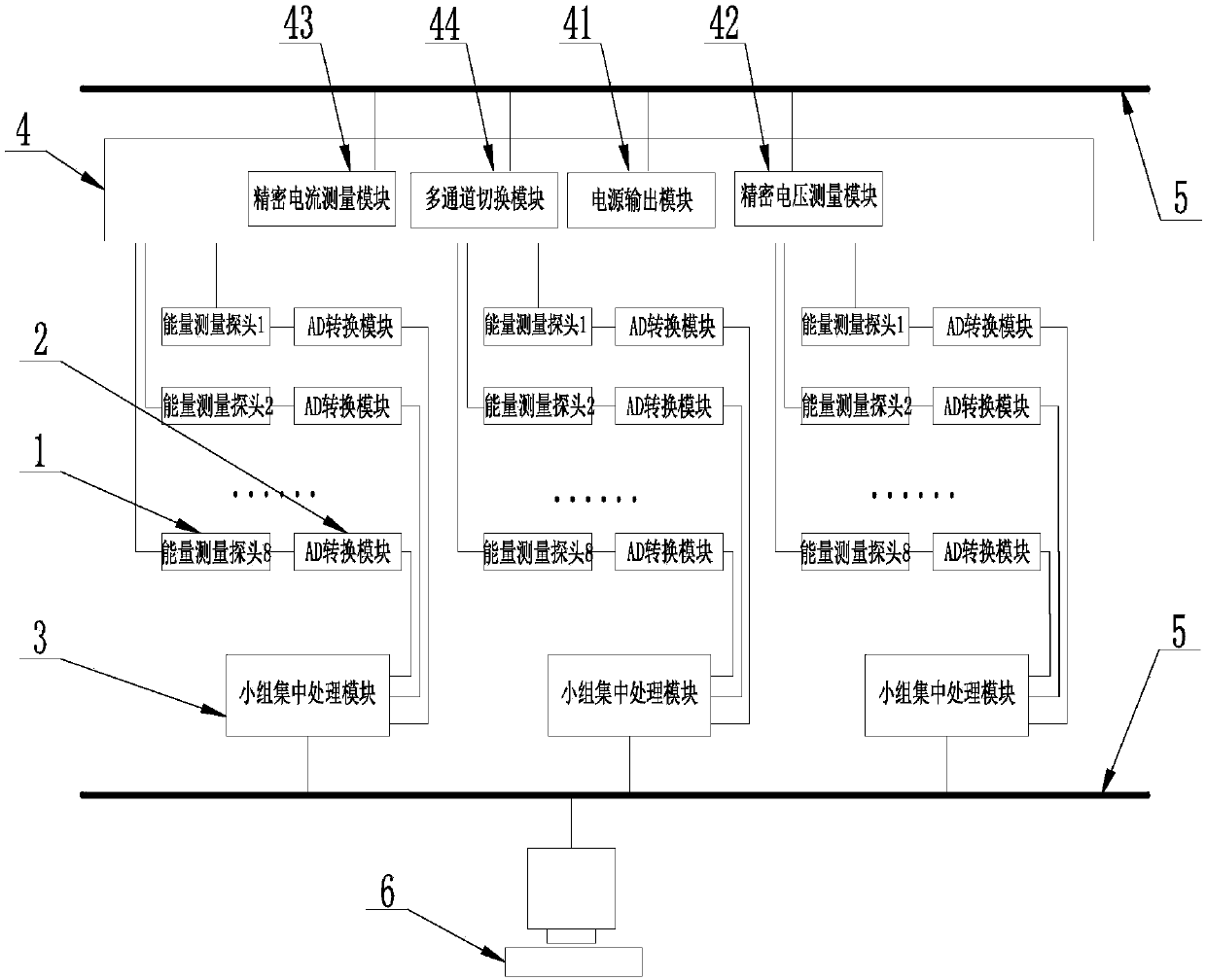
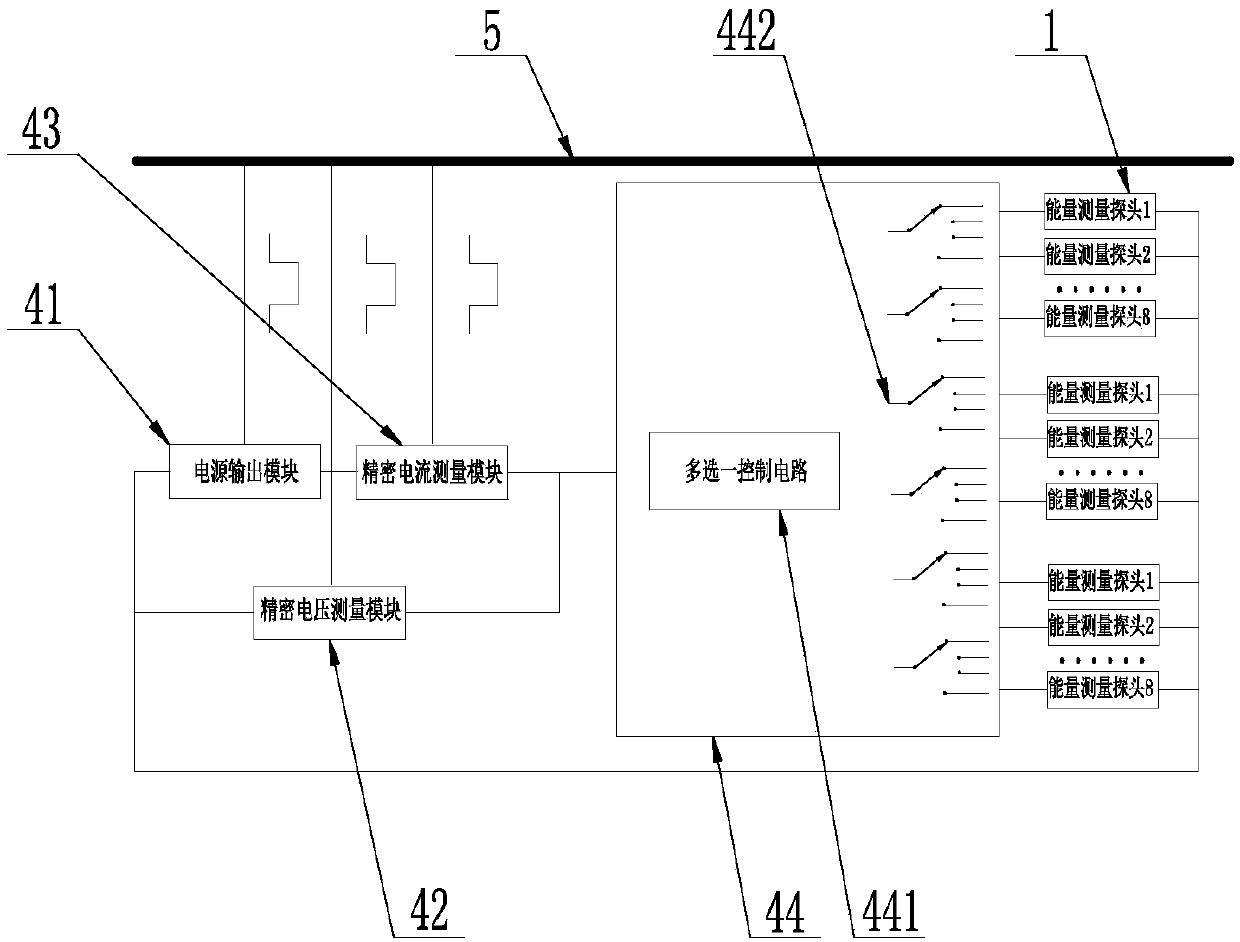
[0027] Such as figure 1 As shown, an energy measurement and calibration system for a large laser device includes an energy measurement probe 1, an AD conversion module 2, a group centralized processing module 3, an energy electrical calibration component 4, a backbone network 5, and an energy measurement and calibration control platform 6. The data transmission interface of the energy measurement probe 1 is sequentially connected to the AD conversion module 2, the group centralized processing module 3, and the backbone network 5. The electrical calibration interface of the energy measurement probe 1 is connected to the backbone network 5 through the energy electrical calibration component 4 The energy measurement and calibration control platform 6 is connected to the backbone network, and the group centralized processing module 3 is used to implement the system's requirements for hierarchical and grouping control, and is responsible for transmitting all data to the energy measure...

Embodiment 2

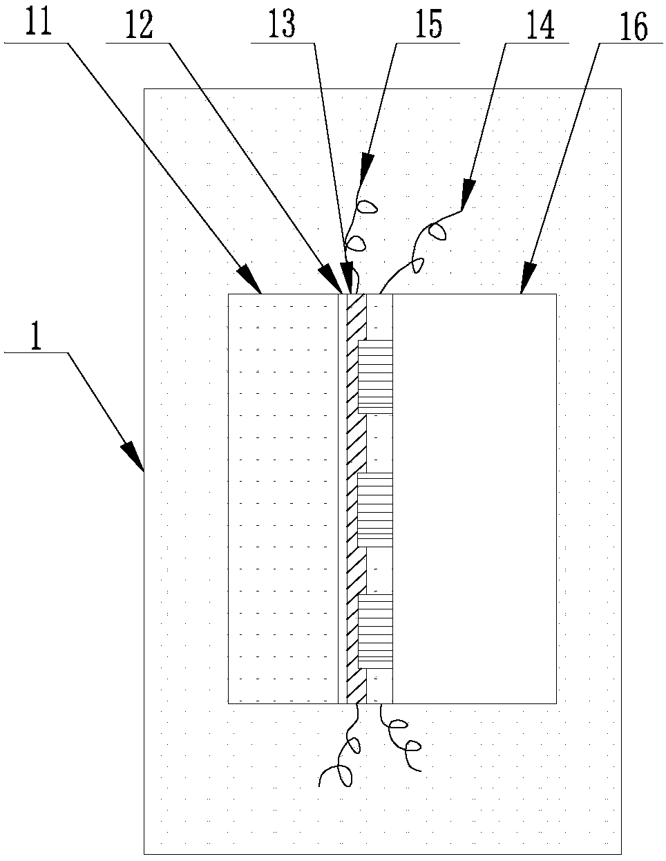
[0038] Such as Figure 5 As shown, the same parts of this embodiment and the first embodiment will not be repeated, the difference is:

[0039] The thin-foil return resistor 15 is arranged in a matrix array alternately with the sensor 14. This arrangement can achieve the same technical effect as the first embodiment.


PUM


Abstract

The invention relates to an energy measurement and calibration system for large laser devices, belonging to the technical field of laser energy measurement, including an energy measurement probe, an AD conversion module, a group centralized processing module, an energy electrical calibration component, a backbone network, and energy measurement and calibration Control platform, the data transmission interface of the energy measurement probe is connected to the AD conversion module, the group centralized processing module and the backbone network in sequence, the electrical calibration interface of the energy measurement probe is connected to the backbone network through the energy electrical calibration component, the energy measurement and The calibration control platform is connected to the backbone network. The invention can satisfy distributed measurement, group control, centralized management and control of data and commands for energy measurement of large multi-channel laser devices, and the calibration process is simple and efficient.

Description

Technical field [0001] The present invention belongs to the technical field of laser energy measurement, and specifically relates to an energy measurement and calibration system for large-scale laser devices. Background technique [0002] High-power solid-state laser devices are required to complete the simultaneous and accurate measurement of laser energy in real time. The measurement feature is that, limited by the optical path structure design, energy measurement probes must be distributed in different spatial positions of the device, that is, distributed measurement; The architecture design of the control system, the multiple beams meeting a certain relationship in space are divided into a group, and unified control is implemented, that is, grouped control; all data and commands are processed by the centralized control system, that is, the centralized control of data and commands. These energy meters must be calibrated regularly. If the optical calibration method is adopted, ...

Claims


Application Information

Patent Timeline
Patent Type & Authority Applications(China)
IPC IPC(8): G01M11/02G01J1/42
CPCG01M11/00G01J1/4257
Inventor 唐菱夏彦文汪凌芳王方彭志涛邓学伟马驰党钊刘华周丽丹房奇袁强胡东霞董军卢宗贵
Owner LASER FUSION RES CENT CHINA ACAD OF ENG PHYSICS
Why Eureka
Try Eureka