
Defect detection control system and method for industrial camera

A defect detection, industrial camera technology, used in optical testing flaws/defects, measuring devices, image data processing, etc.

Inactive Publication Date: 2018-04-20
深圳市创科自动化控制技术有限公司
View PDF3 Cites 35 Cited by
  • Summary
  • Abstract
  • Description
  • Claims
  • Application Information

AI Technical Summary

Problems solved by technology

[0004] In order to overcome the above-mentioned defects, the technical problem to be solved in the present invention is to control the strobe of the light source and to synchronize the photographing, and to use a very complicated image synthesis algorithm when synthesizing multiple images. defective parts and can effectively suppress interference

Method used


Image

  • Defect detection control system and method for industrial camera
  • Defect detection control system and method for industrial camera

Examples


Embodiment Construction

[0023] In the following, embodiments of the present invention are described with reference to the drawings.

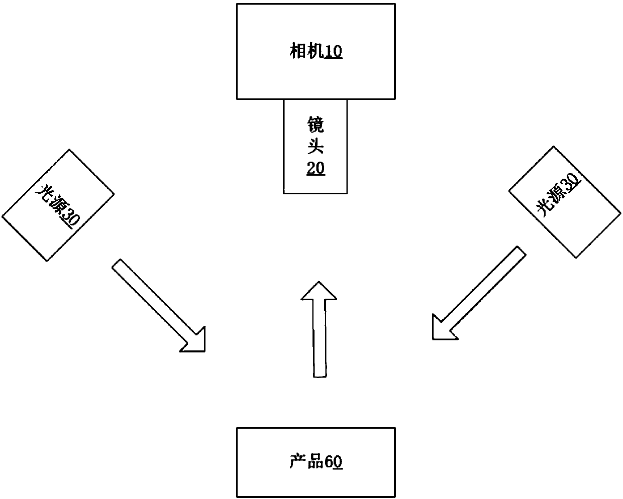
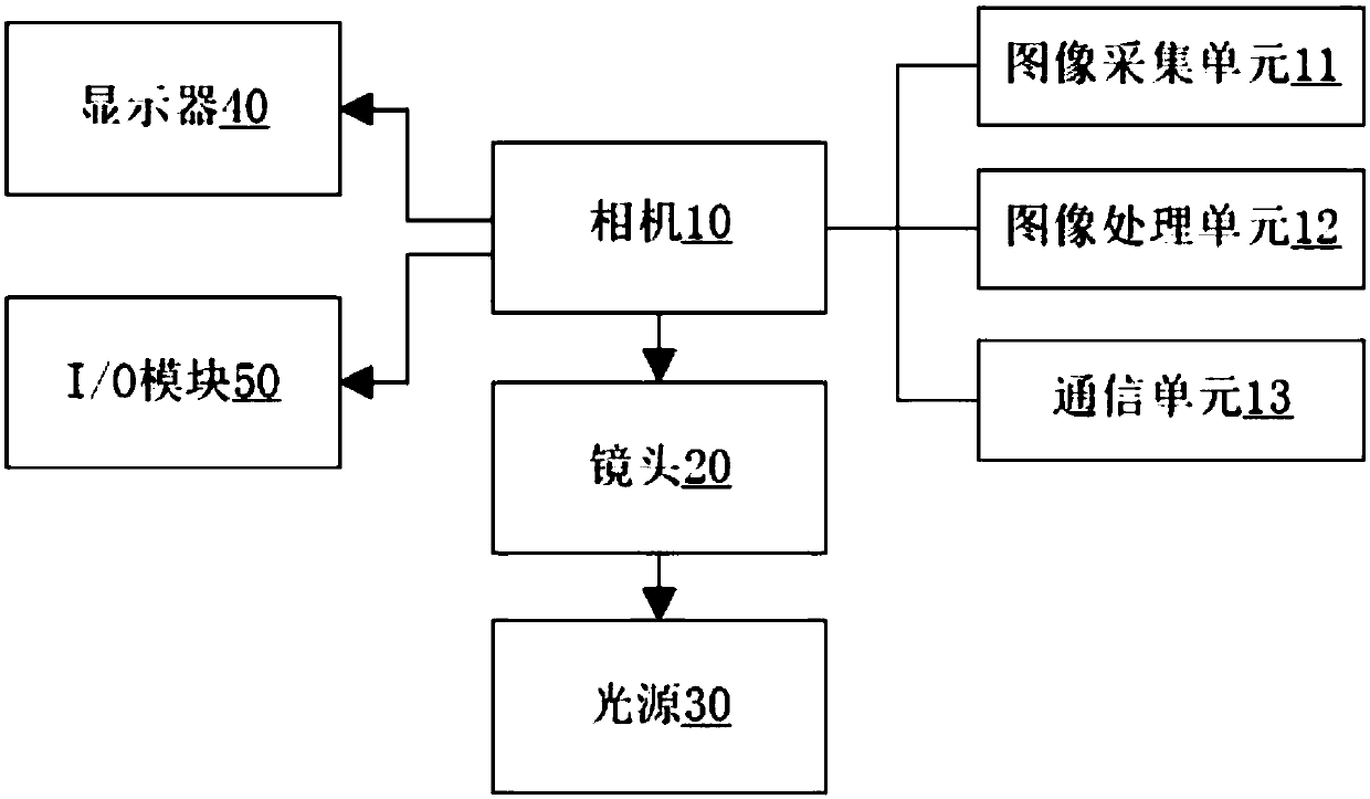
[0024] Such as figure 1 As shown, the defect detection system of an industrial camera includes a camera 10, a lens 20 connected to the camera, and a plurality of light sources 30, wherein the plurality of light sources face the front of the product 60 at different angles, and the main control unit of the camera controls the plurality of light sources The lighting sequence of the camera, and at the same time start the image acquisition unit of the camera to take pictures and generate multiple photos;

[0025] The camera includes an image processing unit, and the image processing unit includes a plurality of fixed modules packaged into algorithms for image processing and comparison of multiple photos;

[0026] The image processing unit has an image synthesis module packaged as a fixed module, a positioning search module, a preprocessing module, a Blob analysis module an...


PUM


Abstract

The invention discloses a defect detection system for an industrial camera. The system comprises a camera, a lens connected with the camera, and multiple light sources, wherein the light sources faceto the front surface of a product at different angles; a main control unit of the camera controls a turn-on sequence of the light sources; an image collection unit of the camera is started to performphotographing to generate multiple images; the camera comprises an image processing unit; and the image processing unit comprises multiple fixed modules formed by packaging algorithms, is used for image processing, and performs synthesis and detection on the images. The system has the beneficial effects that the images shot at multiple angles are synthesized, and product defects are detected out on a synthesized image, so that the problem of incapability of completely detecting out the product defects in conventional single-angle image shooting is solved.

Description

technical field [0001] The invention relates to the field of industrial camera equipment, in particular to an industrial camera defect detection control system and method. Background technique [0002] The traditional defect detection method is to use a light source with a fixed luminous angle for lighting. For the detection of defects such as scratches on the surface of the object, when the direction, thickness and depth of the scratches are inconsistent, the angle of the light source cannot be consistent with the angle of the scratches, resulting in imaging. The effect is not good, which leads to the inability to accurately detect the defect. This method uses multiple angles to light and take pictures separately, and then combines multiple photos to finally obtain an image in which scratches in all directions can be clearly imaged, and through the software Algorithms detect flawed data such as scratches. [0003] In the field of industrial automation, it is often necessar...

Claims


Application Information

Patent Timeline
Patent Type & Authority Applications(China)
IPC IPC(8): G06T7/00G06T7/194G06T7/62G06T7/66G01N21/88
CPCG01N21/8806G01N21/8851G01N2021/8887G06T7/001G06T2207/10004G06T7/194G06T7/62G06T7/66
Inventor 张宜飞
Owner 深圳市创科自动化控制技术有限公司
Learn More