
Temperature protection system for power distribution cabinet

A protection system and power distribution cabinet technology, applied to thermometers, thermometer parts, emergency protection circuit devices, etc., can solve problems such as temperature fires at wiring points, reduced contact area at wiring positions, and increased resistance, so as to prevent electrical Fire protection, the effect of protecting the safety of use

Pending Publication Date: 2018-04-20
珠海浩云电气有限公司
View PDF0 Cites 6 Cited by
  • Summary
  • Abstract
  • Description
  • Claims
  • Application Information

AI Technical Summary

Problems solved by technology

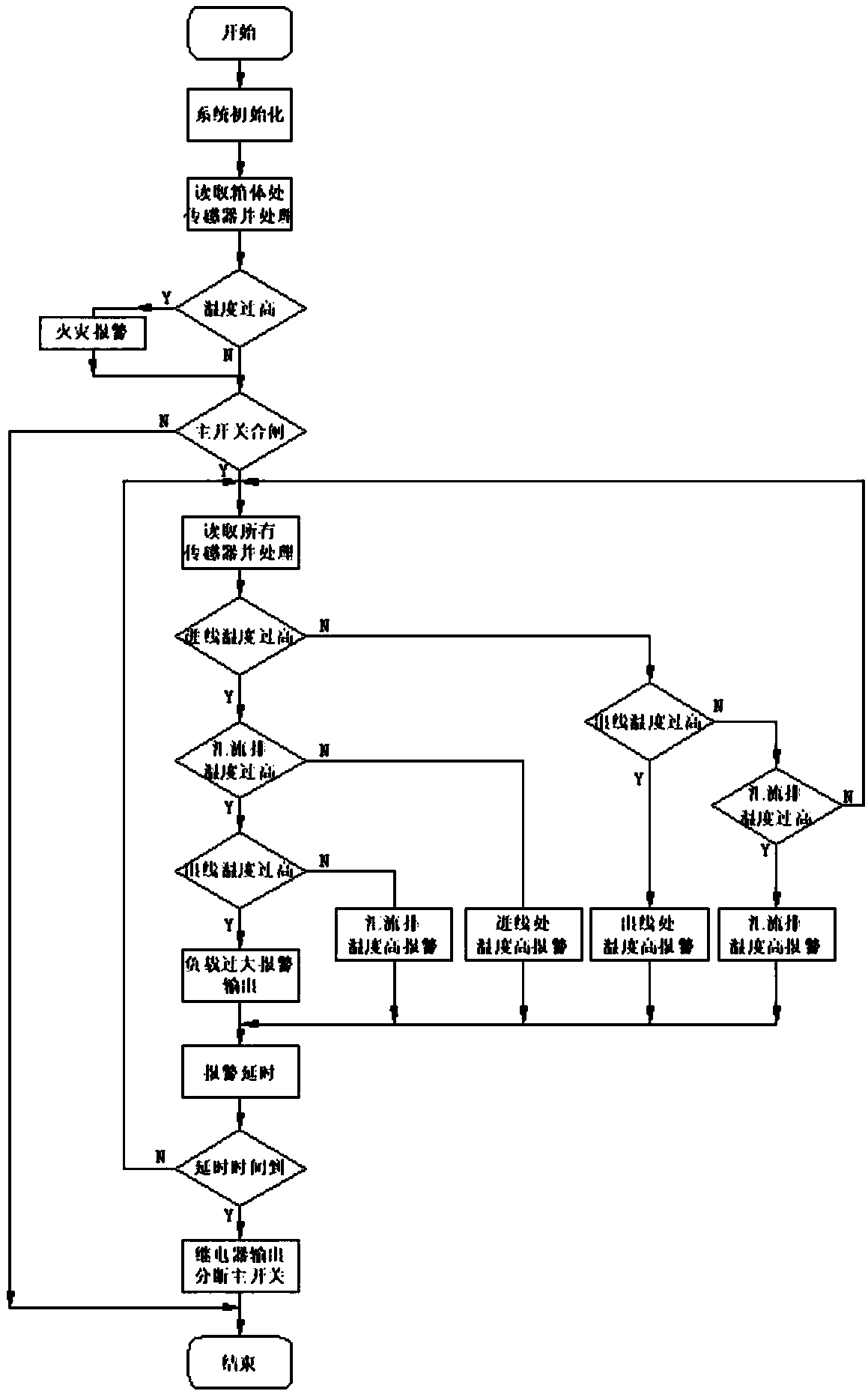
[0002] The heating of electrical appliances in the power distribution cabinet is usually one of the direct causes of fire accidents. For this reason, many switches have an over-current thermal protection function, but the existing switch thermal protection only detects the temperature of the input and output terminals of the switch, and the power distribution cabinet usually The heat is caused by the wiring position of the terminal and the bus bar. Because the contact area of ​​the wiring position is reduced, the resistance increases. When the same current flows, the heat is much higher than other places. When the temperature is transmitted to the bus bar or cable. When the switch caused a trip, the wiring was hot enough to start a fire

Method used


Image

  • Temperature protection system for power distribution cabinet
  • Temperature protection system for power distribution cabinet
  • Temperature protection system for power distribution cabinet

Examples


Embodiment Construction

[0026] The following will clearly and completely describe the technical solutions in the embodiments of the present invention with reference to the accompanying drawings in the embodiments of the present invention. Obviously, the described embodiments are only some, not all, embodiments of the present invention. Based on the embodiments of the present invention, all other embodiments obtained by persons of ordinary skill in the art without making creative efforts belong to the protection scope of the present invention.

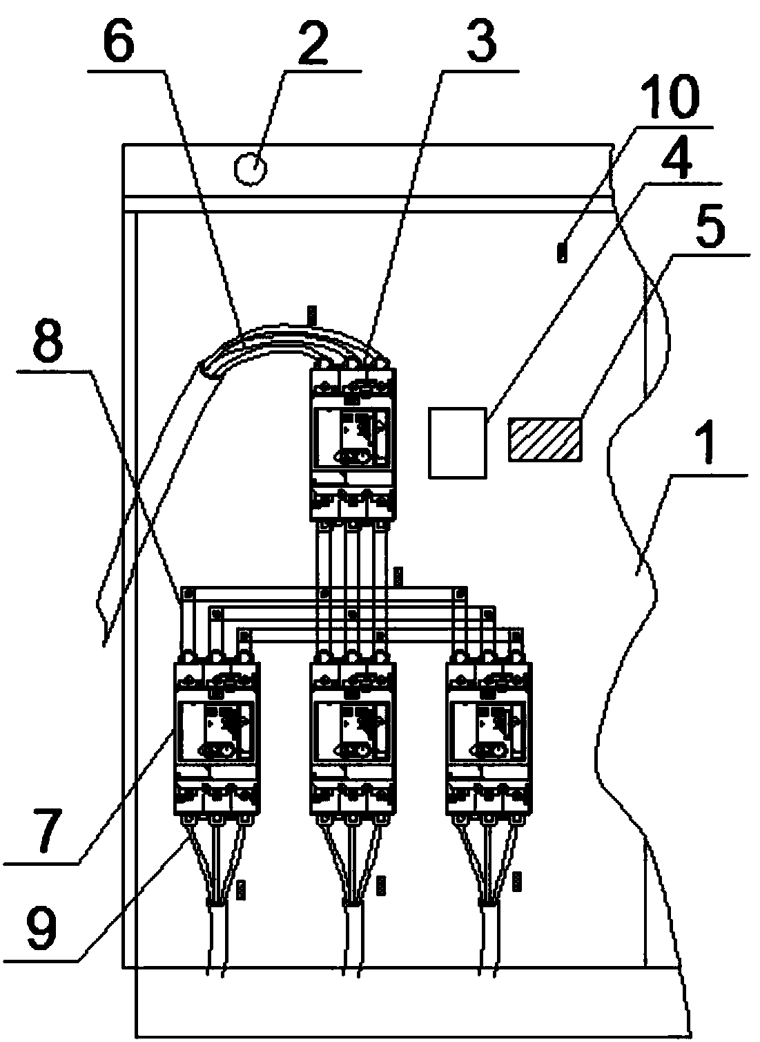
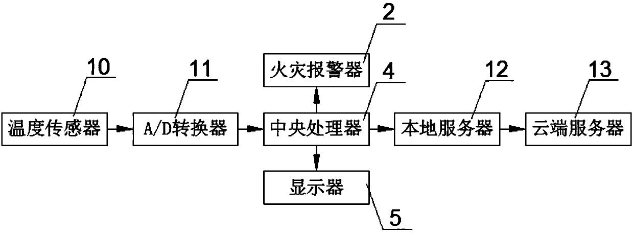
[0027] according to figure 1 A power distribution cabinet temperature protection system shown includes a cabinet body 1, a fire alarm 2 is provided on the top of the cabinet body 1, and a main switch 3, a central processing unit 4 and a display 5 are arranged inside the cabinet body 1, The central processing unit 4 is arranged on one side of the main switch 3, the display 5 is arranged on one side of the central processing unit 4, the side of the main switch 3...


PUM


Abstract

The invention discloses a temperature protection system for a power distribution cabinet, and the system comprises a cabinet body. The top of the cabinet body is provided with a fire alarm, and the interior of the cabinet body is provided with a main switch, a central processor, and a display. The central processor is disposed at one side of the main switch, and the display is disposed at one sideof the central processor. One side of the main switch is connected with an incoming cable, and the bottom of the main switch is provided with a relay. The main switch is connected with a relay through a busbar, and one end of the relay is provided with an outgoing cable. The incoming cable, the outgoing cable, one side of the busbar, and the inner wall of the cabinet body are provided with temperature sensors. The whole system employs a temperature sensor, and employs a CPU to process and output the information and is connected to a main switch control loop of the power distribution cabinet in a parallel manner. There is no need to add excessive electrical circuits and accessories. The system protects the use safety of the power distribution cabinet, and avoids the electrical fire more effectively.

Description

technical field [0001] The invention relates to the field of temperature protection systems, in particular to a temperature protection system for a power distribution cabinet. Background technique [0002] The heating of electrical appliances in the power distribution cabinet is usually one of the direct causes of fire accidents. For this reason, many switches have an over-current thermal protection function, but the existing switch thermal protection only detects the temperature of the input and output terminals of the switch, and the power distribution cabinet usually The heat is caused by the wiring position of the terminal and the bus bar. Because the contact area of ​​the wiring position is reduced, the resistance increases. When the same current flows, the heat is much higher than other places. When the temperature is transmitted to the bus bar or cable. When the switch causes a trip, the wiring is hot enough to start a fire. [0003] Therefore, it is necessary to inv...

Claims


Application Information

Patent Timeline
IPC IPC(8): H02H7/22H02B1/30H02B1/28H02B1/24H02J13/00G01K1/02G01K1/022
CPCH02B1/24H02B1/28H02B1/30H02H7/22G01K1/024G01K1/026G01K1/028H02J13/00001
Inventor 邹浩罗宇明
Owner 珠海浩云电气有限公司
Learn More