Fertilization equipment for rotary tillage

A device and carrier technology, which is applied in the field of rotary tillage and fertilization equipment, can solve the problems of fertilizer exposure to air and waste, and achieve the effects of good fertilization effect, prevention of loss and waste, and prevention of outward loss.

Pending Publication Date: 2018-04-24
台州市智诚工业设计有限公司
View PDF7 Cites 6 Cited by
  • Summary
  • Abstract
  • Description
  • Claims
  • Application Information

AI Technical Summary

Problems solved by technology

[0006] The purpose of the present invention is to address the deficiencies of the prior art, to divert the loose soil to both sides and transfer it backwards through the soil transfer part, and to use the fertilization part to evenly fertilize the soil during the transfer p

Method used


Image

  • Fertilization equipment for rotary tillage
  • Fertilization equipment for rotary tillage
  • Fertilization equipment for rotary tillage

Examples


Embodiment 1

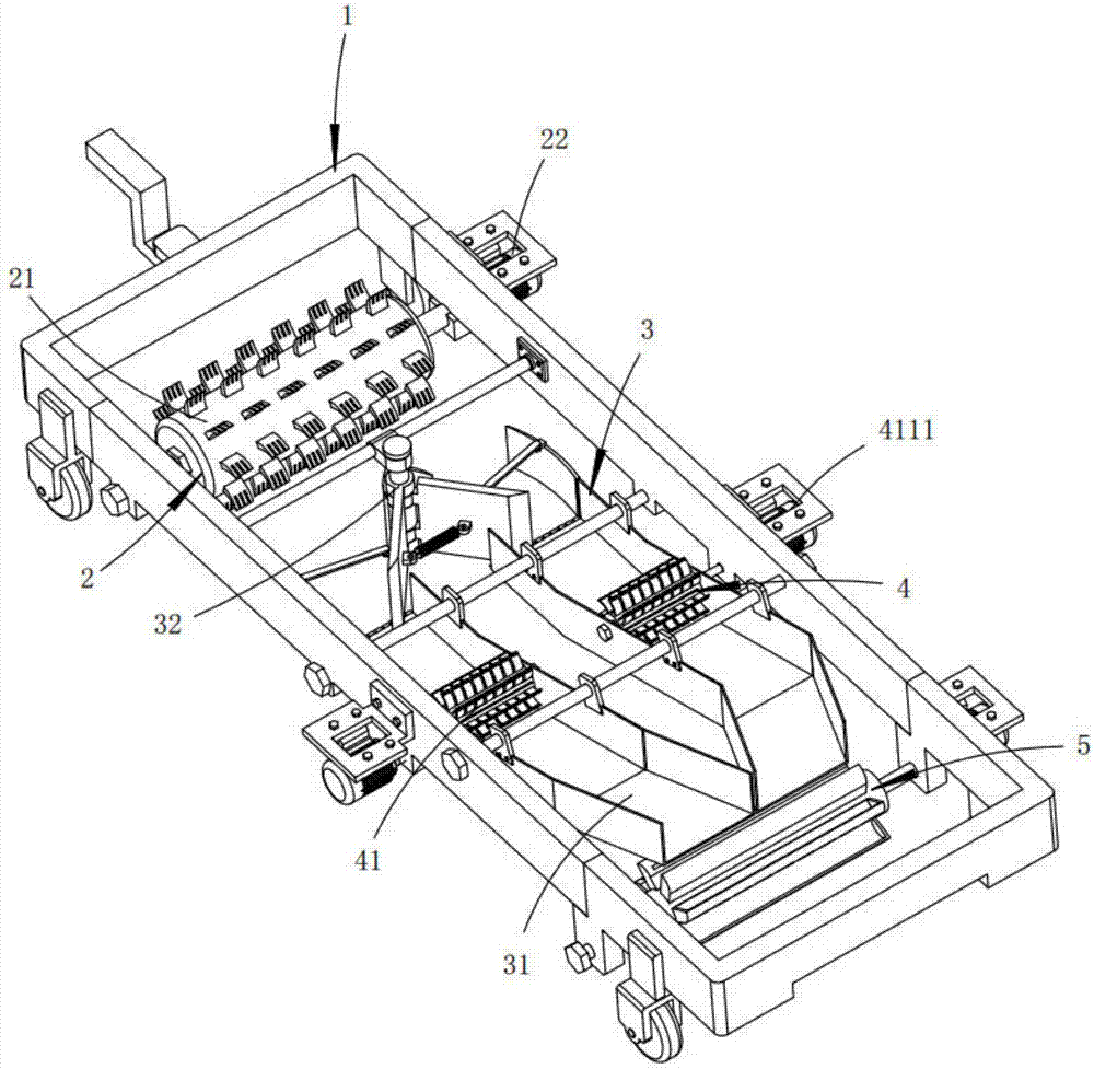
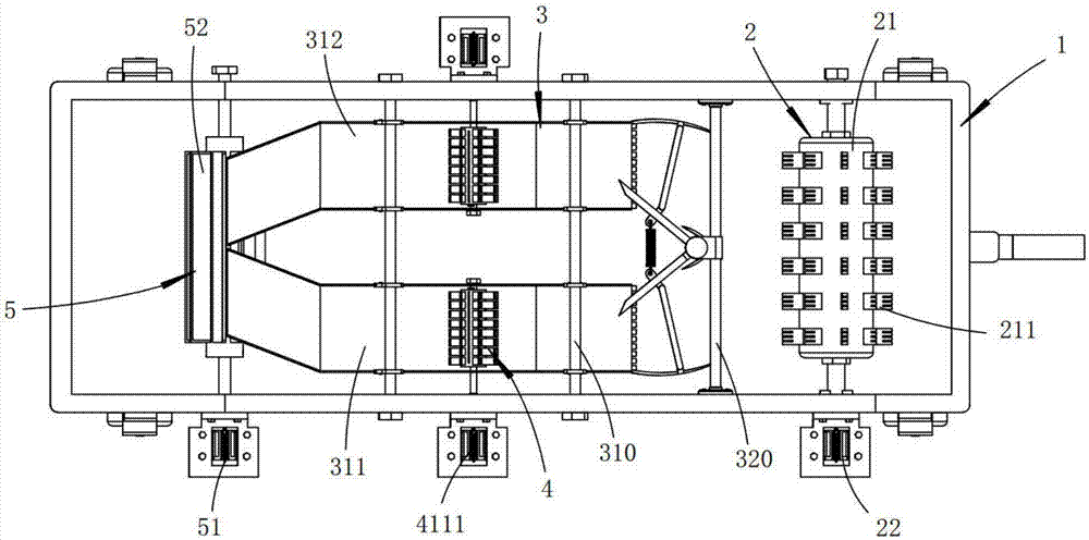
[0061] Such as figure 1 and figure 2 Shown, a kind of rotary tillage fertilization equipment, comprises walking carrier 1, also comprises:

[0062] A soil loosening device 2, which is installed at the front section of the walking carrier 1, and performs loose soil work on the land;

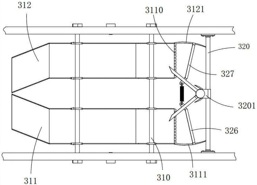
[0063] Soil transfer part 3, described soil transfer part 3 is installed on described walking carrier 1, and it is positioned at the rear of described soil loosening device 2, and it diverts the loose soil that loose soil device 2 produces to both sides and flows to post-transfer;

[0064] The fertilization part 4, the fertilization part 4 is installed on the walking carrier 1, and is located above the soil transfer part 3, which includes a soil shifting device 41 for assisting soil transfer and a soil shifting device 41 interlocked with the Fertilization device 42;

[0065] A soil covering device 5, the soil covering device 5 is installed at the rear part of the walking carrier 1, and is use...

Embodiment approach

[0067] As a preferred embodiment, the loosening device 2 includes:

[0068] The soil loosening part 21, the soil loosening part 21 is horizontally rotated and installed on the walking carrier 1, and a number of loosening rake teeth 211 are arranged around the outer peripheral surface at equal distances along the axial direction;

[0069] The first power part 22, the first power part 22 is fixedly arranged on the traveling carrier 1, and drives the soil loosening part 21 to perform soil loosening work.

[0070] What needs to be explained here is that in this embodiment, it is preferable to set the front ends of the loosening rake teeth 211 in a bifurcated shape. Through this setting, the bulkiness of the soil can be further improved when performing loosening work, which is more conducive to Subsequent fertilizer absorption.

[0071] It should be further explained that, in this embodiment, when the soil loosening member 21 rotates, its tangential movement direction with the gro...

Embodiment 2

[0097] Such as Figure 11 , Figure 12 , Figure 13 and Figure 14 As shown, the components that are the same as or corresponding to those in the first embodiment are marked with the corresponding reference numerals in the first embodiment. For the sake of simplicity, only the differences from the first embodiment will be described below. The difference between this embodiment two and embodiment one is:

[0098] As a preferred embodiment, the inside of the barrel body 521 is also provided with a water storage cavity 5211, and several water inlets 5212 are provided at both ends of the barrel body 521 at equal distances along the circumference. A water inlet 5213 is sleeved, and the water inlet 5213 is fixedly connected with the walking carrier 1, and a water port 5210 is opened at the upper end thereof;

[0099] A number of water outlets 5221 communicating with the water storage cavity 5211 are opened in the bottom side wall of the soil carrying member 522 along its length ...


PUM


Abstract

The invention relates to fertilization equipment for rotary tillage. The fertilization equipment comprises a travelling carrier, a soil loosening device, a soil transfer portion, a fertilization portion and an earth covering device. The soil loosening device is mounted at a front portion of the travelling carrier, and is used for loosening the soil of land. The soil transfer portion is mounted onthe travelling carrier, is located in rear of the soil loosening device, and is used for dividing the loose soil, generated after soil loosening by the soil loosening device, to two sides and transferring the loose soil to the rear side. The fertilization portion is mounted on the traveling carrier, is located above the soil transfer portion, and comprises a scarification device and a fertilization device. The scarification device can assist soil transfer, and the fertilization device is in linkage with the scarification device. The earth covering device is mounted on the rear portion of the travelling carrier, and is used for receiving the soil, outputted backwards by the soil transfer portion, and performing earth covering and irrigation on the soil. The technical problem of waste causedby evaporation of fertilizer after the fertilizer is exposed in the air after conventional fertilization devices are used for fertilization can be solved.

Description

technical field [0001] The invention relates to the technical field of agricultural machinery and equipment, in particular to a rotary tillage and fertilization equipment. Background technique [0002] As the population continues to increase, agricultural planting is becoming more and more important. In order to increase the output of agricultural products, agricultural machinery is constantly being updated. [0003] When the soil cannot provide the nutrients needed for crop growth and development, the act of supplementing the crops with artificial nutrients is called fertilization. When planting crops, due to the repeated planting of crops throughout the year, the nutrients in the soil will continue to decrease with the increase in the number of years of use. For this reason, before planting crops, it is necessary to fertilize the planting farmland. However, the existing fertilizer applicators generally spread the granular fertilizer on the surface of the soil and wait fo...

Claims


Application Information

Patent Timeline
IPC IPC(8): A01B49/06A01B49/04
CPCA01B49/04A01B49/065
Inventor 徐海军
Owner 台州市智诚工业设计有限公司
Why Eureka
Try Eureka